c. In the shortest time possible, place
4. Install insert (41) and press pin (40) until it
stator (lead end up) in an oven and
bottoms into end bell (39), if they were
bring parts to 290 - 325F (143.3 -
removed.
162.8 C).
5. Insert the assembled armature into the
d. Repeat above step (b).
assembled end bell. Then install the end
bell on housing (53).
e. In the shortest time possible, place
stator (lead end up) in oven at 290
6. Insert rod assemblies (38) with washers
- 325F (143.3 - 162.8C). The
(37) through end bell assembly, then
stator temperature must reach 290
install insulators (36).
- 300F (143.3 - 148.9C) for 1-3/4
to 2 hours.
7. Align the scribe mark on end bell (30) with
scribe mark on housing (53). Tap end bell
5. Ground test using 500 volts AC.
into place with rawhide mallet. Push rod
assemblies (38) through end bell (30) and
C. Lubrication.
install nuts (34) and washers (35). Torque
nuts (34) to 12-15 inch-pounds.
No lubrication required.
Ball bearings are
8. Install bearing (33), retainer (32) and
sealed units, lubricated at the factory and
screws (31) torqued to 20-25 inch-pounds.
cannot be relubricated.
Use sealing compound primer and sealant
on threads.
9. Install inserts (29) into terminal (28) if they
were removed, then with brush holder
(27), washer (26) and screw (25), fasten
the terminal to insulator ring (16) with the
deep chamfer on the I.D. of the insulator
on the same side as the holder (27).
Across the insulator 180, repeat these
instructions and install another terminal
(28) and holder (27). These are positive
brush holders.
10. Install brush holder (24), screw (23),
washer (22) and nut (21). Install the
remaining brush holder in a like manner,
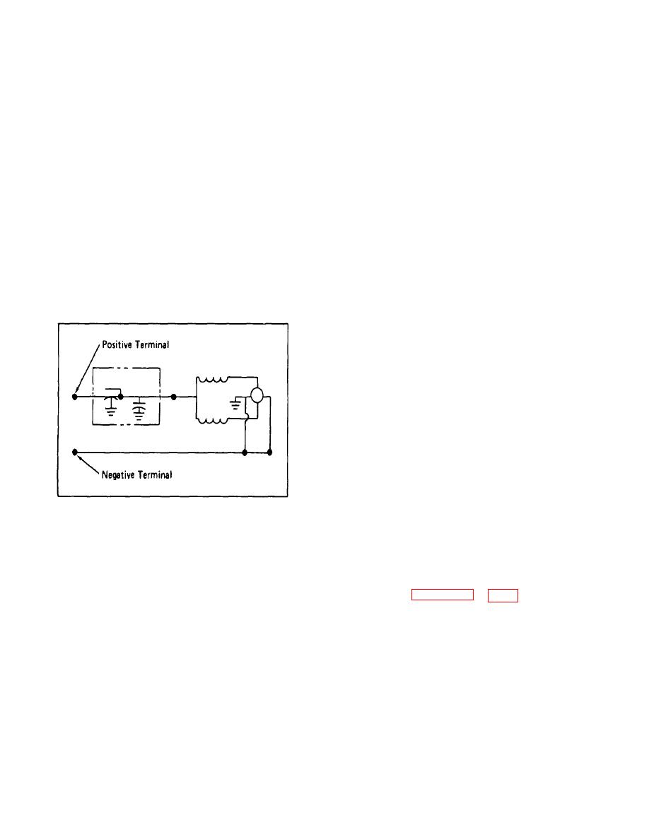
Figure A-2 . Electrical Wiring Schematic
180 across insulator ring (16). These are
negative brush holders.
A-6.
REASSEMBLY.
11. Install two springs (20) on spring holder
A. General.
(19) and insert holder through insulator
ring (16). Install washer (18) and nut (17),
Reassemble the motor (Fig. A) generally in the
reverse order of the index numbers which
springs and spring holders.
represent the order of disassembly.
12. Torque nuts (21) and (17) to 25-29 inch-
1. Assembly of fields into the stator housing
pounds Torque screws (25) to 40-46 inch-
was accomplished during repair and
pounds.
replacement.
13. Align the assembly with one positive
2. Set housing (53) in base (46) and install
brush holder centerline rotator 45
screws (45) torqued to 80 to 100 inch-
clockwise from the scribe mark on the
pounds.
side of end bell (30). Install washers (15)
and screws (14) torqued to 20-25 inch-
3. Install insert (43) if it was removed. Press
pounds.
bearing (44) on armature (42).
14. Install screws (12), washers (13) and
A-6


