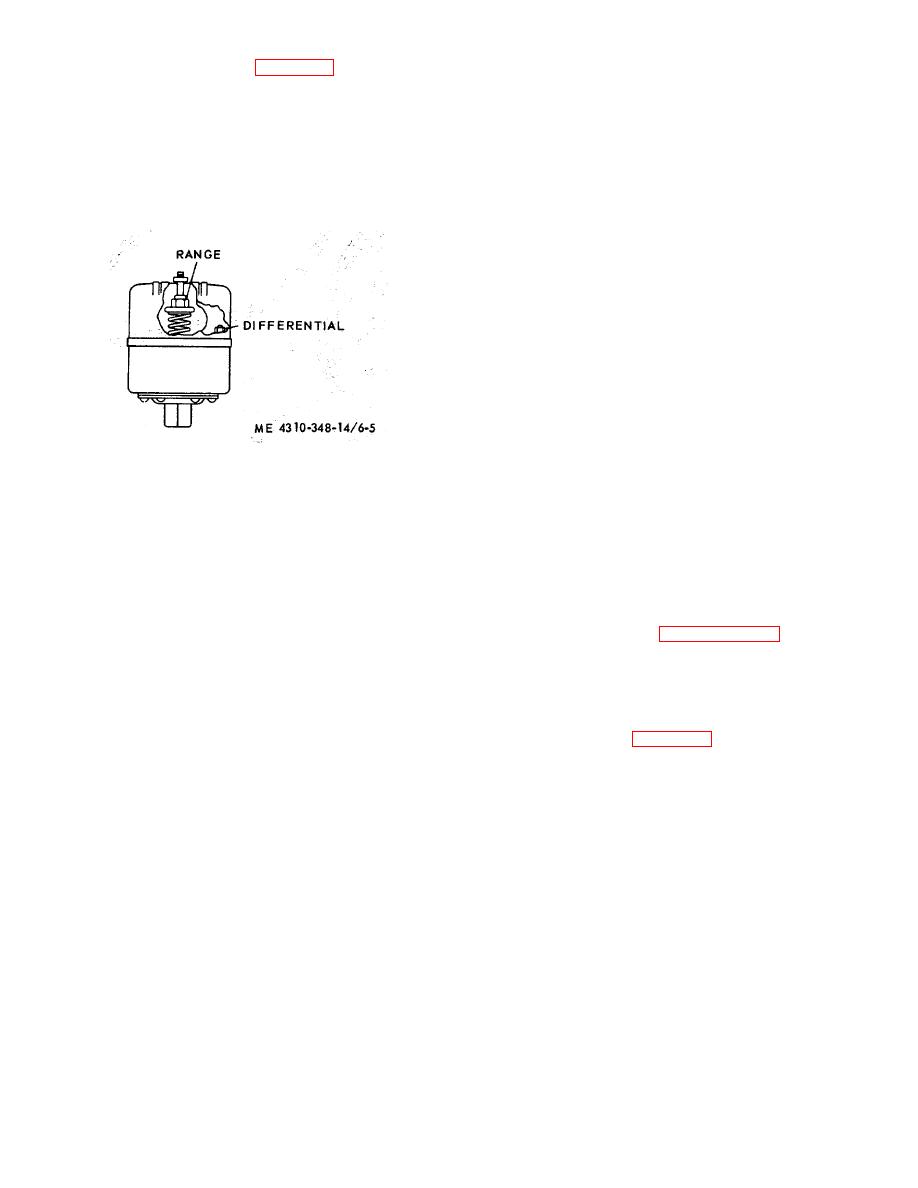
There is interaction between these two adjustments.
b. Installation. Refer to figure 6-4 and reverse the
If the cut-out is increased, so will the differential
removal procedures to install the pressure switch.
increase. Or, if the differential is reduced, the cutout
will be reduced. This factor must be considered, and
c. Adjustment. The pressure switch has a cut-out
compensated for when adjusting.
adjustment and a differential adjustment. The cut- out is
the pressure at which the switch contacts open, and the
(1) Increase the cut-out point by turning the
differential is the span between the cut-in and cut-out
range nut (fig. 6-5) clockwise.
settings.
(2) Decrease the cut-out point by turning the
range nut counterclockwise.
(3) Note the pressure gage readings at which
the motor starts or stops. Re-establish the differential
setting if necessary.
(4) Increase the differential by turning the
differential (fig. 6-5) nut clockwise. Turning the nut
counterclockwise decreases the span.
NOTE
It is advisable to have as wide a
differential as possible to avoid
frequent starting and stopping of the
NOTE
compressor.
Section II. AIR COMPRESSOR
ease in starting, and to minimize wear on bearings and
6-5. General
shaft of the drive motor.
The air compressor is a 2-cylinder, 2-stage air cooled
compressor. It has a capacity of 5 cfm at 610 rpm, and
6-6. Air Compressor
the electric motor drive cuts-in at 175 psi.
The
compressor stops when the air pressure gage indicates
a. Removal Refer to paragraph 4-10 and remove
200 psi, plus or minus 5 psi. The compressed air is
the air compressor.
cooled by a finned inter-cooler tube between the first
stage cylinder and the second stage cylinder. The second
b. Disassembly.
stage compression is cooled by an aftercooler tube on its
way to the air receiver. These tubes remove most of the
heat of compression before the air reaches the receiver.
(1) Refer to figure 6-6 and remove fanwheel,
The compressor is equipped wiih a centrifugal unloader
aftercooler, and the intercooler in numerical sequence.
and pilot valve system, to unload/ internal pressure for
6-7


