TM 5-4310-367-14
CYLINDER HEAD, CYLINDER AND VALVE - continued
ACTION
LOCATION/lTEM
REMARKS
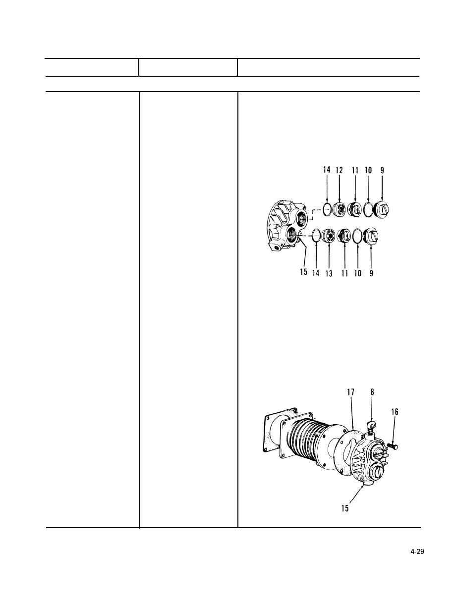
4-25. ASSEMBLY continued.
Install in high pressure head
2 gaskets (14)
5.
(15).
CAUTION
Exhaust valve must go in
valve chamber of head adja-
cent to the tubing connector
of the aftercooler. Intake
valve must go in valve
chamber adjacent to inter-
cooler tubing connector.
Reversal can damage pump
by creating excessive pressure
in the cooler.
Install in high pressure head
Intake vavle (12) and
6.
(15).
exhaust valve ( 13)
Install in high pressure head
1 valve retainer (11),
7.
(15).
2 gaskets (10) and
2 caps (9)
a. Assemble with gasket
High pressure head (15)
8.
(17).
b. Install with 4 screws (16).
Install in cylinder heads.
9.
3 elbows (8)


