TM 5-4310-370-14
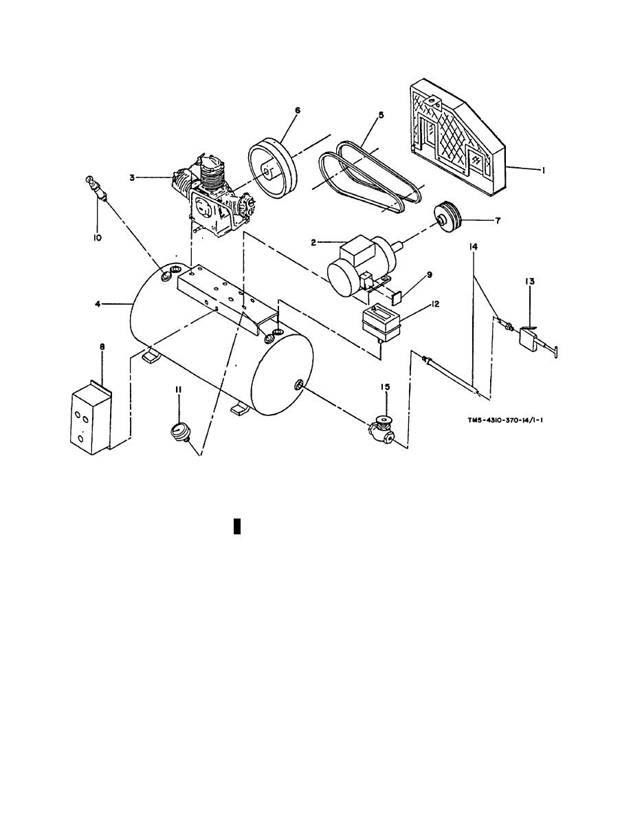
1.
Belt Guard
6. Flywheel
11.
Pressure Gage
2.
Motor
7. Motor Pulley
12.
Pressure Switch
3.
Compressor Pump
8. Starter Switch
13.
Inflator Gage
4.
Air Receiver
9. Junction Box Cover
14.
Inflator Gage Hose
5.
V Belts
10. Safety Relief Valve
15.
Globe Valve
FIGURE 1-1. COMPONENT IDENTIFICATION
(3) The Air Receiver Plate is located on the air receiver and lists manufacturer's name, National Board Number,
model number, year of manufacture, and working pressure.
b. Tabulated Data, Operator Maintenance
WEIGHTS AND DIMENSIONS
Weight ..................................................................................... 390 lbs.
(177.3 kg)
Length, Overall ......................................................................... 48 in.
(121.9 cm)
1-2 Change 1


