TM 5-4310-384-13
b.
Remove the belt guard cover. Refer to paragraph 3-23.
c.
Remove the V-belts. Refer to paragraph 3-24.
d.
Remove the capscrews (1) securing the bushing (2) to the pulley (3).
e.
Thread capscrews (1 ) into jacking holes (4) and tighten evenly until bushing and pulley separate.
NOTE
Apply a thin coat of oil to shaft to ease bushing removal.
f.
Remove bushing and pulley from shaft.
g.
Remove key (5) from shaft.
INSTALLATION.
a.
Install key (5) in shaft keyway.
b.
Place pulley (3) into position with aligning key.
c.
Place bushing (2) on shaft and align unthreaded holes in bushing with threaded holes in pulley.
d.
Thread capscrews (1) into pulley (3).
e.
Before tightening capscrews, align drive pulley grooves with flywheel grooves. Refer to next paragraph.
f.
Tighten capscrews evenly until bushing is seated and pulley is secure.
ALIGNMENT.
a.
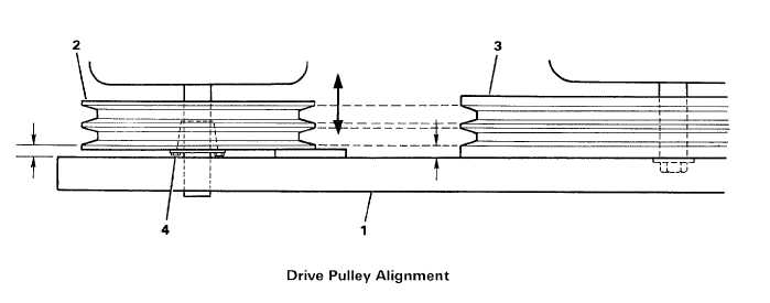
Place straightedge (1) across compressor flywheel (2) and drive pulley (3).
b.
Measure distance from straightedge to flywheel outer belt groove.
c.
Loosen capscrews on drive pulley and move drive pulley on motor shaft so that pulley outer belt groove is same
distance from straightedge.
d.
Tighten capscrews (4) after alignment.
3-31


