TM 5-4310-451-14
4-61. WIRING HARNESS REPAIR.
This Task Covers:
a.
General
d.
Male Connector Repair
b.
Identification Band Replacement
e.
Female Connector Repair
c.
Terminal Replacement
Initial Setup:
Equipment Conditions:
Materials/Parts:
•
Battery cables disconnected (see paragraph 4-60).
•
Insulation sleeving (Item 23, Appendix E)
Tools/Test Equipment:
•
Solder (Item 37, Appendix E)
•
General mechanic's tool kit
•
Identification bands (as required)
•
Common no. 1 shop set
•
Terminals (as required)
a.
GENERAL
1. A switch or sending unit Is more likely to be defective than a gage or Indicator. The least likely cause of a problem
would be In the wiring or harness.
2. Before performing any tests of circuits, you must read and understand paragraph 4-5.
3. When Installing a replacement wire, ensure that wire Is the same gage as the wire being replaced. Identify the
new wire by using color-coded tape that matches the color of the wire replaced. Match type and size of
connectors from old wire to new wire.
4. If a wire Is spliced, use Insulation sleeving to Insulate area spliced. Use a suitable heat source to shrink Insulation
sleeving.
5. Perform continuity test on new wires before Installing them into the unit.
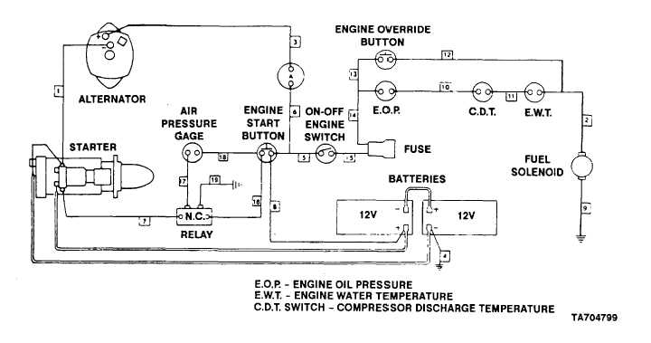
6. Refer to wiring diagram when performing electrical troubleshooting and when performing electrical repair and
maintenance.
4-134


