TM 5-4310-452-14
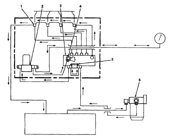
1-14. FUEL SYSTEM (Con't).
1. Injector
4. Solenoid Valve
2. Fuel Filter
5. Metering Fuel Pump
3. Injection Pump
6. Fuel/Water Separator
1-15. AIR COMPRESSOR.
a.
The air compressor is an enclosed helical, single stage, positive displacement-type.
b.
Air is compressed when two oil-flooded helical rotors (male and female) on parallel shafts mesh in an enclosed
housing with air inlet and outlet ports located on opposite ends of the housing. The male rotor has four lobes, 90° apart,
and the female rotor has six grooves, 60° apart. The grooves of the female rotor mesh with and are driven by the male
rotor. Thrust bearings at the rear of the shafts prevent lengthwise movement of the rotors. When the engine turns the
compressor, the rotors mesh and free air is drawn into the cavities between the male rotor lobe and the grooves of the
female rotor. The air is trapped in these cavities and follows the direction of rotation of each rotor. When the air inlet
port closes, the compression cycle begins and the trapped air is compressed and directed to the opposite or discharge
side of the rotor housing. In a metered flow, cooled lubricating oil is injected into the rotor housing so that it moves with
the air being compressed. This removes much of the heat of compression and causes the air discharge temperature to
be lower. From the discharge port, the compressed air and lubricating oil go to the oil separator which serves as an oil
and air storage reservoir, For a further description of the lubrication system, see paragraph 1-16.
TA505390
1-14