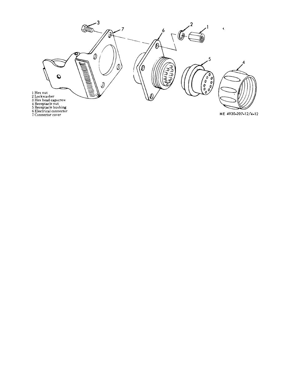
Figure 4-12. Intervehicular receptacle, disassembly
and reassembly.
c. Reassembly.
illustrated in figure 4-12.
(1) Reassemble the blackout-stoplight and tail-
light as illustrated in figure 4-11.
out-stoplight, taillights, lamps and wiring harness
as illustrated in figure 4-10.
(2) Reassemble and install the intervehicular
receptacle in the reverse of numerical sequence as
Section V. FUEL AND EXHAUST SYSTEM
4-19. General
equipped with an exhaust diverter, which serves as a
muffler, connected directly to the engine exhaust
a. Fuel System. The lubricating unit is equipped
system. This diverter is used to direct exhaust gases
with a positive-feed, pressure type fuel system. The
into a heat reservoir below the lubricant tanks, for
fuel system consists of a fuel filter, fuel tank, fuel
cold weather operation, or to the atmosphere.
pump, carburetor, air cleaner, governor and gover-
4-20. Fuel Tank, Filter and Lines
nor controls. Refer to TM 5-2805-203-14 for main-
tenance on the fuel pump, carburetor, air cleaner,
a. Removal.
governor and governor controls.
(1) Open the fuel shut-off cock (29, fig. 4-13) and
b. Exhaust System. The lubricating unit is
drain the fuel tank (27).
4-15


