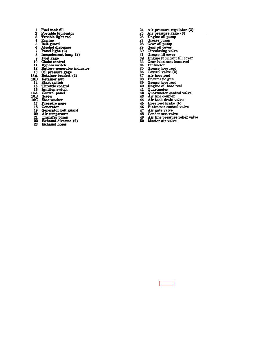
Figure 2-3. Continued.
t. Air Line Coupler. The air line coupler
pressure to its respective pump and is grad-
(43) on the air reel end is used to supply com-
uated to indicate from O to 200 psi.
pressed air to the various air-operated acces-
p. Condensate Valves. A manually operated
sories.
condensate valve (48) is mounted on the side
u. Air Tank Drain Valve. A m a n u a l l y
of each pump, and is used to discharge accumu-
operated air tank drain valve (44 ) is mounted
lated moisture from the pump air motor, Turn
on the accessory drawer frame and is directly
the valve "handle counterclockwise to dispel
connected to the air receiver to facilitate drain-
moisture.
ing air and moisture from the air receiver.
q. Circulating Valve. A circulating valve
v. Air Receiver Pressure Gage. The air re-
(30) is mounted on the lower housing of each
ceiver pressure gage (17 ) is located on the air
pump, and permits the bypassing and circu-
pressure tank. The gauge is graduated from 0
lating of lubricants with the pump, returning
directly into the lubricant compartment. To
to 300 psi and should show a pressure of 150
to 175 psi for proper operation of the equip-
open the circulating valve, turn the valve
ment.
handle counterclockwise two full turns.
w. Air Line Pressure Relief Valve. The air
r. Control Valve. A control valve (36) is
line pressure relief valve (49) is located at the
attached to each grease line. Depress the trig-
air receiver on the right side of the lubricating
ger on the control valve to dispense grease and
unit. The relief valve releases air pressure in
release the trigger to halt flow.
the air receiver when it exceeds 200 psi. When
s. Meters. A pintmeter (34) is attached to
this valve opens, the pressure on gage (17) will
the gear oil hydraulic line control valve (46).
drop.
A quartmeter (41) is attached to engine oil
x. Master Air Valve. The master control
hydraulic line control valve (42). Depress the
valve (22, fig. 3-8) is located next to the al-
trigger on each control valve to dispense the
cohol dispenser and is operated by a push-pull
lubricants and release the trigger to halt lubri-
plunger. The master control valve allows air
cant flow. Amount dispensed is registered on
to be directed through the alcohol dispenser to
respective meter.
2-7


