TM 5-4930-218-14
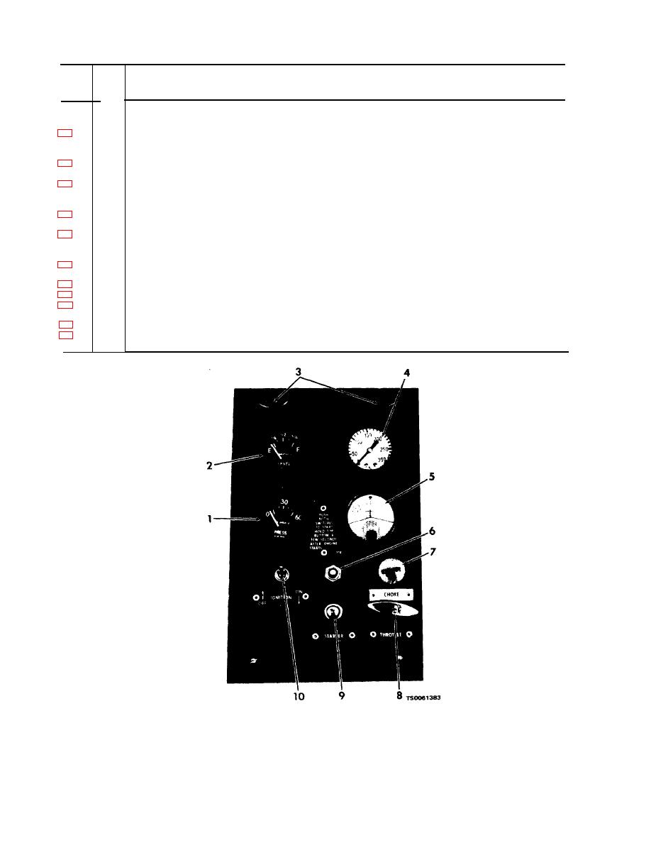
Table 2-1. Controls and Instruments -- Continued
Index
Fig.
Description
No.
No.
valve to charge pump with lubricant at starting. Close during dispensing operation. One circulating valve is provided in
each pump.
AIR PRESSURE REGULATOR. Adjusts air pressure applied to lubricant pump. When pressure is increased, it causes
1
lubricant to be discharged at higher pressure. Adjust pressure to provide proper lubricant flow from dispensing nozzle.
One regulator is provided for each lubricant pump.
AIR PRESSURE GAGE. Indicates air pressure applied to lubricant pump to permit pressure adjustment to predeter-
2
mined setting.
GEAR OIL PINT METER DISPENSER. Provides a method of dispensing a metered amount of gear oil. Dial pointer must
1
be adjusted to zero before dispensing. Squeezing trigger causes oil to be dispensed. Dial pointer indicates pints of oil
dispensed.
2
GREASE DISPENSER. Controls dispensing of chassis lubricating grease. Squeezing the trigger causes grease to flow
from the nozzle. Two grease dispensing hose reels are provided.
ENGINE OIL QUARTMETER DISPENSER. Provides a method of dispensing a metered amount of engine oil. Dial point-
3
er must be adjusted to zero before dispensing. Squeezing trigger causes oil to be dispensed. Dial pointer in-
dicates quarts of oil dispensed.
4
AIR RECEIVER DRAIN VALVE. Drains moisture and air from air receiver. Turn counterclockwise to open valve, clock-
wise to close.
AIR HOSE QUICK-DISCONNECT COUPLER. Supplies connection for quick-disconnect air tools and chucks.
5
6
HOSE REEL LOCK. Locks hose reel to prevent excessive hose from unwinding. One lock is provided for each reel.
1
ENGINE EXHAUST DIVERTER. Controls flow of engine exhaust either to provide warming for the lubricant dispensing
tank or to divert the exhaust directly to the atmosphere.
2
AIR RECEIVER SHUTOFF VALVE. Controls the flow of air from the air receiver.
AIR PRESSURE SAFETY VALVE. Protects the air receiver and the compressor intercooler from excessive air pressure.
1
Pulling out on the valve ring releases air and provides a check of the valve operation.


