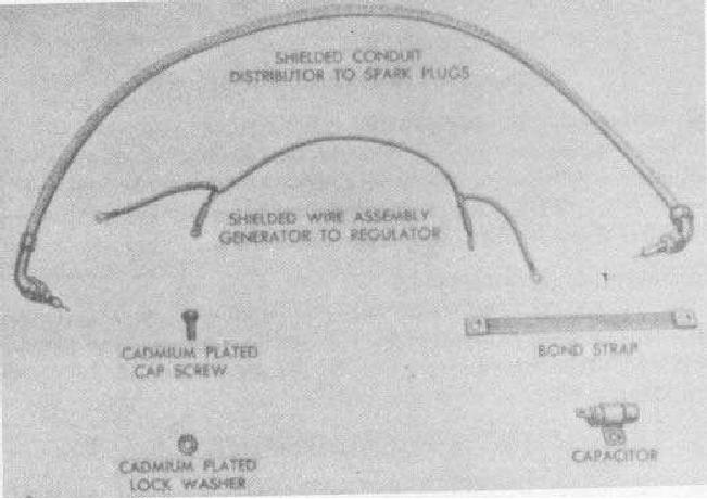
and from voltage regulator to generator. All battery cables are shielded.
b. Bonding. All cable clamps and bonding straps are securely attached with bolts and external toothed lockwashers.
Bonding straps are installed at the following points:
(1) One bond strap from the compressor support frame to the bolt which attaches magnetic switch to battery
box.
(2) One bond strap from instrument panel to hood top.
(3) Two bond straps from radiator to compressor supp ort frame.
(4) Two bond straps from front engine support to upper oil pan.
(5) Two bond straps from rear engine support to compressor support frame.
(6) One bond strap from voltage regulator support to crankcase upper oil pan.
(7) One bond strap from voltage regulator ground to generator stud.
c. Capacitor. A capacitor is connected from the center voltage regulator terminal to the frame. It filters the spark
discharge and prevents electrical radiation.
Figure 17. Radio suppression components.
56

