
b. Disassembly (fig. 43). Clamp the square flange of the filter base (4) in a vise and unscrew the filter top (1).
Remove the screens (2) and felt disk (3) from the base.
c. Cleaning and Inspection. Clean all parts thoroughly with compressed air. Make certain that the screens are not
damaged in any way. Do not get oil on the felt.
d. Reassembly (fig. 43). Place the felt disk (3) between the two screens (2) and insert these parts into the filter base
(4). Clamp the square flange of the base in a vise, and screw on the filter top (1).
e. Installation (fig. 41). Screw the elbow (5) into the control line air filter (6) and screw the filter into the unloader pilot
(26). Connect the tube assembly (4) to the elbow.
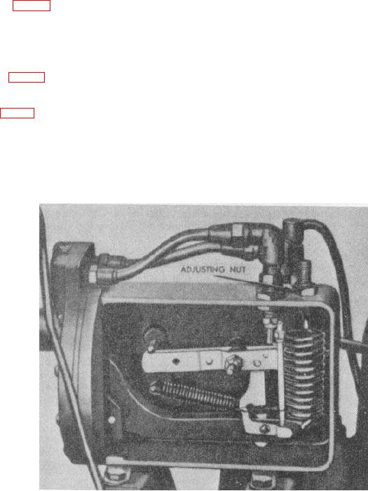
107. Unloader Pilot Adjustment
The pressure control system must be set to load at 90 psi and unload at 100 psi. The adjustment must be made with
the engine-compressor in operation and while observing the pressure on the air receiver pressure gage. Turning the
Figure 44. Adjusting the unloader pilot.
107