TM9-4310-396-13
Section III - PRINCIPLES OF OPERATION
1-11
COMPRESSOR OPERATING PRINCIPLES.
1-11.1
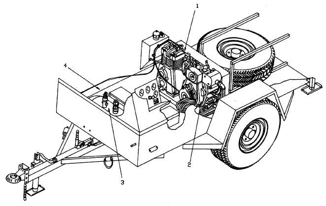
Compressor (1. Figure 1-3). The compressor compresses air to put out a minimum of 15 cfm at 175 psi. It is
driven by the diesel engine through two belts from the pulley contained on the engine. The belt guard protects the
operator from injury and the engine pulley and compressor flywheel from damage.
1-11.2
Engine (2). The compressor is driven by a diesel engine. The engine drives the compressor by two V-belts
attached to a clutch/pulley connected to the shaft of the engine. The engine is equipped with both an electrical starter
and a manual recoil starter to allow engine start. The operating speed is factory set for a constant operating speed while
compressing air and a throttling device to slow the engine while operating not loaded. The electric starter is powered by
a 12 VDC battery.
1-11.3
Air Receiver (3). The air receiver stores the compressed air delivered from the compressor. It is equipped
with a check valve, high pressure relief valve, and a line pressure gage. The receiver is also equipped with a tank drain
to drain moisture or compressed air. The discharge line leads to the exterior of the trailer and is fitted with a quick air line
disconnect where the air hose is attached. The air hose then transports the compressed air to the point of use by the
operator.
1-11.4
Compressor Trailer (4). The compressor trailer provides a means to transport the compressor as well as a
support base for the equipment. It is provided with two wheels with brakes and a spare tire. The enclosure of the trailer
provides protection of the compressor, engine, and components.
Figure 1-3. Operating Principles.
1-6


