TM 9-4310-397-14
2-2. INDICATORS.
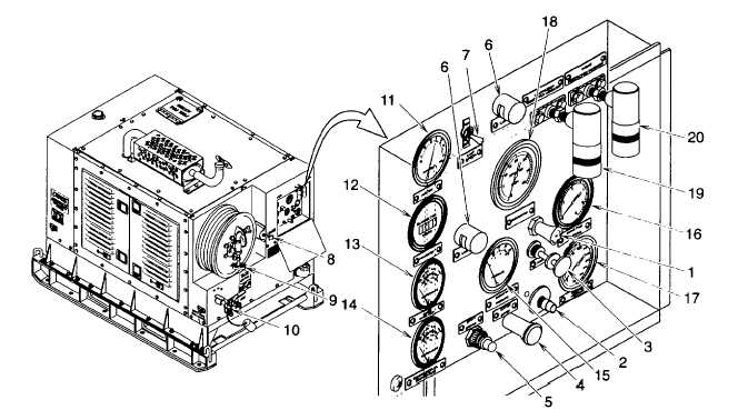
The information that follows references the indicator components found in Figure 2-1.
a.
Ammeter. The AMMETER (11) measures the rate of charge or discharge of the battery, normal operating
reading 0 to +15 amperes.
b.
Hourmeter. HOURMETER (12) records operating time in hours and tenths of an hour.
Figure 2-1. Operator's Controls and Indicators
c.
Engine Water Temperature Gauge. ENGINE WATER TEMPerature gauge (13) indicates the temperature of the
engine coolant. Normal operating range is 180°F to 200°F (82°C to 93°C) and the internal trip sensor is set at 220°
F(105°C). The manual reset button must be pressed after temperature drops below this set temperature before engine
restart.
d.
Compressor Oil Temperature Gauge. The COMPRESSOR OIL TEMPERATURE gauge (14) indicates the
temperature of the compressor system oil. Normal operating range is 160°F to 225°F (71°C to 107C). The high
temperature safety switch is set at 230°F (110°C) and will shut off fuel supply to the engine if that temperature is
reached. The manual reset button must be pressed after the temperature has dropped before the unit can be restarted.
e.
Engine Oil Pressure Gauge. The ENGINE OIL PRESSURE gauge (15) indicates the engine lubricating oil
pressure. Normal reading is 60 psi to 100 psi (4.2 kg/cm2 to 7.0 kg/cm2).
f.
Engine Fuel Pressure Gauge. The normal operating range for the ENGINE FUEL PRESSURE gauge (16) is 4 to
6 psi. (.28 kgs/cm2 to .42 kgs/cm2).
g.
Receiver Pressure Gauge. The RECEIVER PRESSURE gauge (17) indicates the air pressure in the oil
separator tank. Normal operating range is 70 to 120 psi. (4.9 kgs/cm2 to 8.4 kgs/cm2).
2-3


