TM 9-4310-397-14
(j)
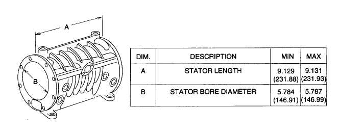
Stator.
Figure 5-12. Stator
d.
Assembly.
(1)
If removed, install eyebolt (Figure 5-2, 46) in top of stator (51).
(2)
Assemble the two drain valves (50), springs (49), new preformed packing (48) (item 29, appendix H) and
drain valve plugs (47) in stator (51).
(3)
Place steel ball (44) in end of stator (51). Coat new preformed packing (45) (item 30, appendix H) with
petrolatum (item 12, section II, appendix E) or equivalent, and place on end of stator (51).
(4)
Preassemble rotor (37), shaft (36), and nonintake end cover (40) by pressing inner race of bearing (39) if
removed, onto shaft (36) until it bottoms on shaft shoulder.
(5)
Assemble nonintake end cover (40) onto shaft (36); install outer race of bearing (39).
CAUTION
Assemble rotor (37) onto shaft (36) with blade slot drain holes on rotation leading edge as
noted at disassembly. Rotation is always toward the side of stator (51) where oil filter and
bypass is mounted.
(6)
Place key (38) in shaft keyway and slide rotor (37) onto shaft (36).
(7)
Press inner race of bearing (22) onto end of rotor shaft (36) until it bottoms on shaft shoulder.
5-13


