
excess wear and deterioration.
c. Installation.
(3) Clean tube; inflate and inspect for
(1) Reassemble wheels, tire, and tube as
leaks. Repair or replace tube as re-
illustrated in figure 3-12.
quired.
(2) Install on rotary compressor is illus-
trated in figure 3-14.
Section X. VIBRATION AND SHOCK INSULATION
General
The engine and blower frame are mounted
on four elastomer shock mounts.
These
shock mounts are fastened to the rotary com-
pressor frame and provide protection against
shock loads imposed on the unit and reduce
engine vibration to a minimum.
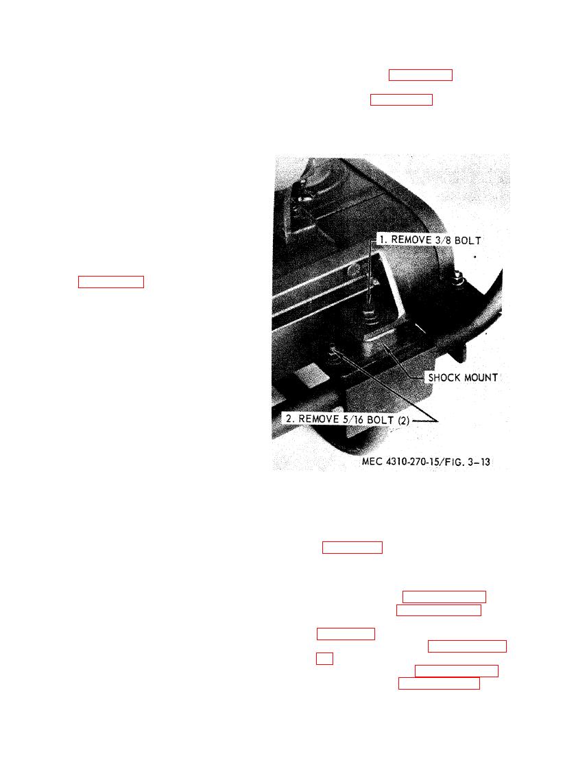
3-42. Shock Mounts
a. Removal. Remove shock mounts as illus-
trated in figure 3-13.
b. Cleaning and Inspection. Clean and inspect
shock mounts for cracks and deterioration.
c. Installation. Install shock mounts as illus-
trated in figure 3-13.
Section XI. FRAME
(1) Remove blower, paragraph 5-14.
3-43. General
(2) Remove engine, paragraph 5-13.
The frame is of an all-welded construction
(3) Remove blower and engine frame,
and fabricated of steel tubing. The structure
is braced and provision is made for shockproof
(4) Remove shock mounts, paragraph 3-
mounting of the engine and blower frame as-
sembly.
(5) Remove fuel tank, paragraph 3-36.
a. Removal.
(6) Remove wheels, paragraph 3-40.

