
TM 5-4310-276-14
(7) Repair any broken or frayed wiring and
(4) Inspect the dielectric block for cracks,
terminals. Repair or replace the coil or rotating
breaks, and proper mounting (Models 1A08-1 and
magnet if damaged or defective.
1A08-2).
(8) Proceed to next paragraph and remove
(5) Inspect the noise filter for serviceability
bearing cap assembly.
and proper mounting (Model 1A08-3). Check con-
tinuity between terminal end to terminal end.
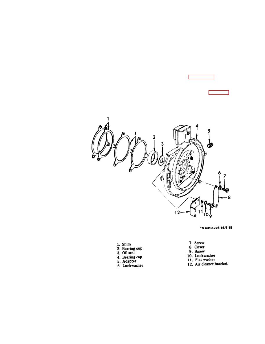
6-17. Bearing Cap Assembly
a. Removal and Disassembly.
NOTE
Continuity should not be read from terminal end
case.
three nuts securing the bearing cap to the engine.
Remove the bearing cap.
(6) Inspect for damaged terminal ends and
frayed wiring (Model 1A08-3).
(2), and oil seal (3). Discard oil seal.
(5) Remove screw (9), lockwasher (10), flat-
(3) Remove adapter (5) from bearing cap (4).
(4) Remove screw (7), lockwasher (6) and
washer (11), and air cleaner bracket (12).
cover (8).
b. Cleaning and Inspection.
6-21

