
TM 5-4310-276-14
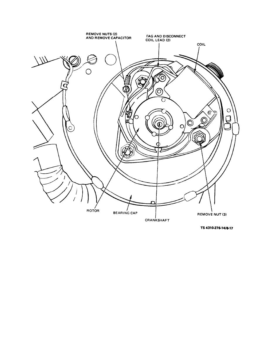
(3) Remove coil clamps and remove coil.
wiring, Using a multimeter or similar device, check
(4) Remove screws and capacitor.
for continuity between leads. Continuity between
(5) Disconnect low-tension cable lead and re-
leads indicates the primary and secondary windings
move cable and grommet from behind bearing cap.
are shorted, therefore, discard the coil.
(6) Use a suitable puller and remove the rotat-
(2) Inspect the rotating magnet for evidence
ing magnet from the crankshaft and remove the
of chaffing, corrosion, proper alignment or damaged
key from crankshaft.
keyway.
b. Inspection and Repair.
(3) Inspect the pole shoes for proper align-
(1) Inspect the coil for proper mounting, evi-
ment, corrosion or evidence of chaffing.
dence of overheating, defective insulation, or frayed
6-20

