
TM 5-4310-335-14
(b)
Apply grease, MIL-G-4343B, to preformed
packings (3, 9 and 12).
(c)
Torque outlet body (14) to 75 inch-pounds
(.8713 kg-m) - 175 inch-pounds (2.0330 kg-
m). Do not lockwire until completion of
testing.
(d)
Test the valve as follows:
WARNING
Exercise extreme care when working with high
pressure air to prevent injury to personnel or
damage to equipment. Do not attempt to tighten
any fitting or perform any work on equipment
when the system is under pressure. Do not
tamper with any pressure relief valves.
1.
Using only clean moisture-free air and
a suitable safety enclosure, plug the
outlet valve and apply 4950 psi
(347.99 kg per sq cm) pressure to the
inlet.
Maintain pressure for one
minute.
Relieve the pressure and
examine the valve. No deformation or
permanent set is permissible.
connecting the outlet port to a non-
recoil tee fitting. Connect a regulated
high pressure air source to the inlet
port. Slowly increase the pressure at
the valve inlet until the valve opens.
This cracking pressure shall be 1625
psi (114.24 kg per sq cm)-1825 psi
(128.30 kg per sq cm). Repeat this
check twice.
3. Perform a room temperature static
leakage check by plugging the outlet of
the valve. Apply 3300 psi (300 kg per
sq cm) air pressure to the inlet.
Immerse the valve in water and obtain
leakage rate from static seals. This
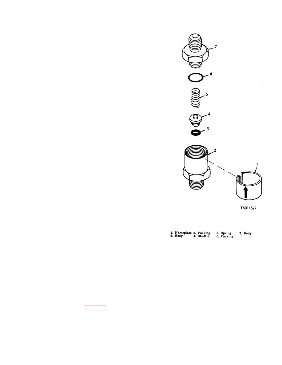
Figure 6-10. Check Valve Assembly
rate shall not exceed 3 cc per hour.
Relieve pressure and remove the plug.
4. Perform a room temperature seat
leakage check by attaching a non-
recoil tee to the outlet port. Apply
1000 psi (70.30 kg per sq cm) air
pressure to the inlet port and immerse
the unit in water. Measure the leakage
rate from the outlet. This rate shall not
exceed 500 cc per minute.
(e) Lockwire the valve.
(2)
Check Valve. (fig. 6-10).
(a) Assemble the valve in the reverse order of
the disassembly procedure, observing the
following additional precautions.
(b) Coat preformed packings (3 and 6) with
grease, MIL-G-4343B.
6-18

