
TM 5-4310-354-14
TS 5-4310-14/4-9
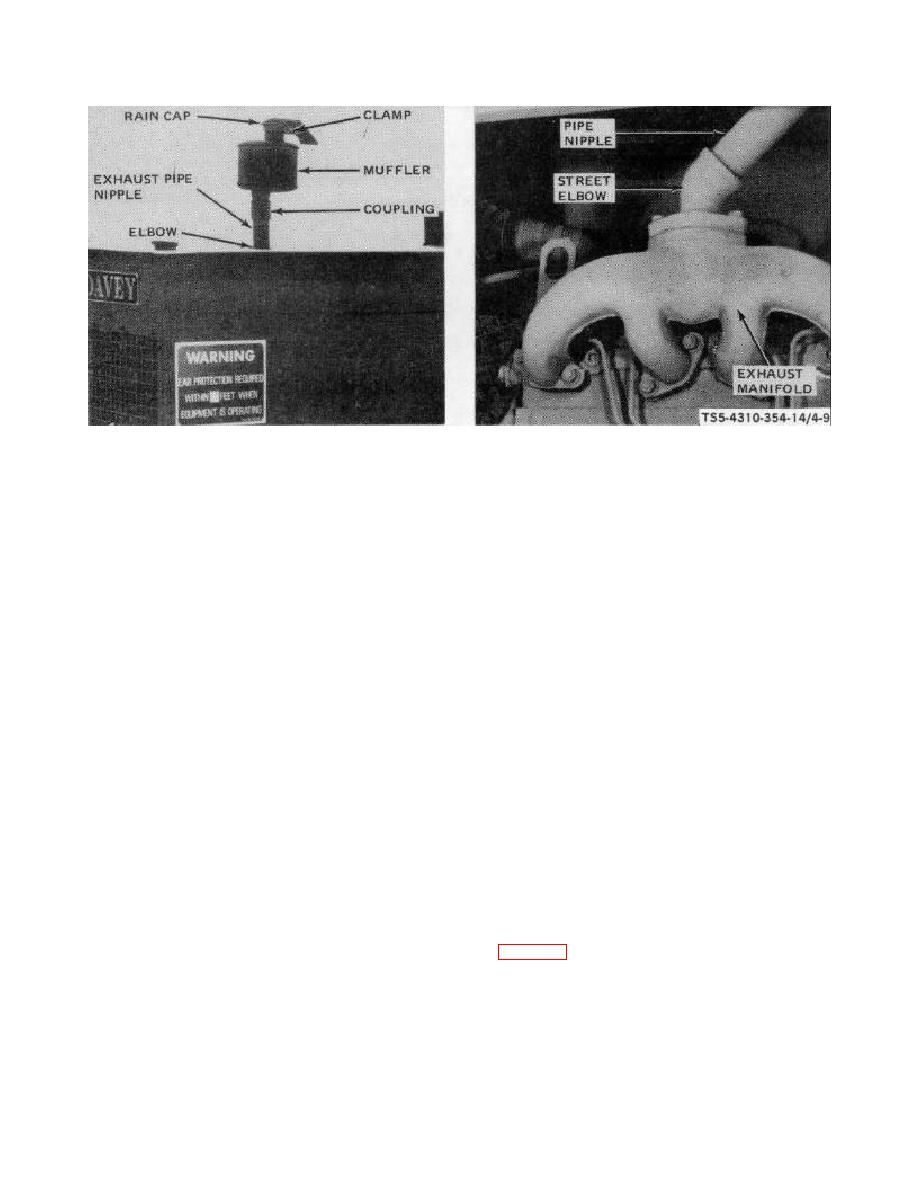
A MUFFLER AND EXHAUST EXTENSION
B EXHAUST MANIFOLD INSTALLATION
REMOVAL
STEP 1.
AS NECESSARY, INSTALL STREET
ELBOW
IN
ENGINE
EXHAUST
STEP 1.
LOOSEN NUT ON RAIN CAP CLAMP,
MANIFOLD, INSTALL PIPE NIPPLE,
TAP RAIN CAP WITH A HAMMER AND
ELBOW, NIPPLE, AND COUPLING.
REMOVE RAIN CAP FROM MUFFLER.
STEP 2.
INSTALL
EXHAUST
MUFFLER
IN
STEP 2.
UNSCREW AND REMOVE MUFFLER
COUPLING.
FROM EXHAUST PIPING COUPLING.
STEP 3.
INSTALL RAIN CAP ON MUFFLER AND
STEP 3.
AS
NECESSARY,
UNSCREW
AND
TIGHTEN CLAMP NUT.
REMOVE PIPE COUPLING, NIPPLE,
ELBOW, NIPPLE, AND STREET ELBOW
FROM ENGINE EXHAUST MANIFOLD.
b. Cleaning and Inspection.
WARNING
(1) Use a wire brush to remove all scale
Dry cleaning solvent, P-D-680, used
deposits and carbon.
After brushing,
to
clean
parts
is
potentially
clean parts in cleaning solvent, Federal
dangerous
to
personnel
and
Specification P-D-680, Type II.
property.
Avoid repeated and
prolonged skin contact. Do not use
(2) Inspect parts for cracks, breaks, or any
near open flame or excessive heat.
other defects.
Flash point of solvent is 100 F-138 F
(38 C - 59 C).
in figure 4-9.
4-24

