
TM 5-4310-354-14
b. Cleaning and Inspection.
Clean the intake
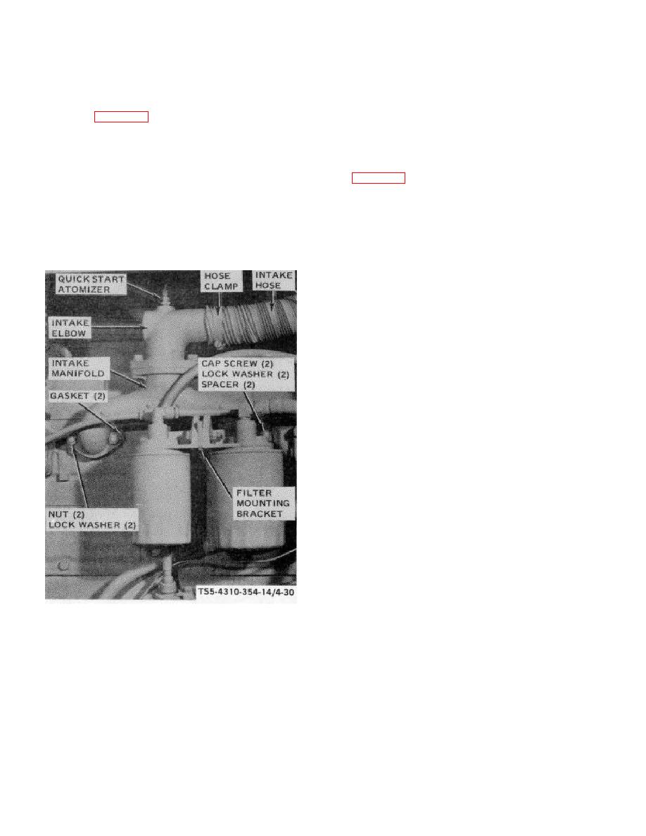
4-46. Intake Manifold.
manifold with solvent, Federal Specification P-D-680,
a. Removal. Remove the engine intake manifold
Type II. Dry thoroughly. Make certain gasket surfaces
as shown in figure 4-30.
on manifold and cylinder head are clean. Inspect the
manifold for cracks, distortion, breaks, and mounting
hardware for damaged threads.
WARNING
c. Installation. Install the intake manifold as shown
Dry cleaning solvent, P-D-680, used
in figure 4-30.
to
clean
parts
is
potentially
dangerous
to
personnel
and
property.
Avoid repeated and
prolonged skin contact. Do not use
near open flame or excessive heat.
Flash point of solvent is 100 F-130 F
(38 C-59 C).
STEP 2.
REMOVE
CAP
SCREWS,
LOCK
WASHERS,
AND
SPACERS
THAT
ATTACH FILTER MOUNTING BRACKET
AND INTAKE MANIFOLD TO CYLINDER
HEAD. CAREFULLY LAY FUEL AND OIL
FILTER ASSEMBLY OUT OF THE WAY OF
MANIFOLD REMOVAL.
STEP 3.
REMOVE
NUTS,
LOCK
WASHERS,
INTAKE MANIFOLD, AND GASKETS
FROM ENGINE. DISCARD GASKETS.
INSTALLATION
STEP 1.
USE NEW INTAKE MANIFOLD GASKETS;
INSTALL
GASKETS
AND
INTAKE
MANIFOLD ON ENGINE. SECURE WITH
LOCK WASHERS AND NUTS.
NOTE
WHEN
INSTALLING
MANIFOLD
MOUNTING HARDWARE, TIGHTEN
NUTS AND CAP SCREWS LIGHTLY
AT FIRST; THEN, STARTING AT
CENTER OF MANIFOLD, WORK
TS5-4310-354-14/4-30
OUTWARD
TIGHTENING
PROGRESSIVELY IN STEPS TO 30
TO 40 FOOT-POUNDS TORQUE.
REMOVAL
STEP 2.
POSITION FUEL AND OIL FILTER
STEP 1.
LOOSEN
HOSE
CLAMP
AND
ASSEMBLY AND INSTALL SPACERS,
DISCONNECT ENGINE INTAKE FLEXIBLE
FILTER MOUNTING BRACKET, LOCK
METAL HOSE. REMOVE QUICK START
WASHERS, AND CAP SCREWS.
ATOMIZER FROM INTAKE ELBOW.
STEP 3.
INSTALL QUICK START ATOMIZER IN
INTAKE ELBOW.
INSTALL ENGINE
INTAKE FLEXIBLE METAL HOSE AND
TIGHTEN HOSE CLAMP.
Figure 4-30. Intake manifold, removal and installation.
4-58

