
TM 5-4310-354-14
4-71. Fuel Injection Pump Solenoid.
a. Removal. Notify Direct Support Maintenance if
removal of fuel injection pump solenoid is necessary.
b. Cleaning and Inspection.
(1) Wipe the fuel injection pump solenoid with
a clean, dry cloth.
(2) Inspect the solenoid lead terminals and
wire connections for evidence of shorts
and for tightness of terminal connections.
(3) Make certain solenoid is wired properly
(refer to figure 1-3).
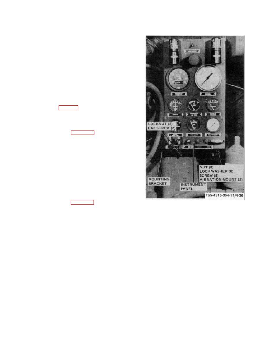
4-72. Instrument Panel Vibration Mounts.
a. Removal.
Remove the instrument
panel
vibration mounts as shown in figure 4-36.
b. Cleanin g and Inspection.
(1) Wipe the vibration mounts with a clean,
dry cloth.
(2) Inspect the mounts for deterioration, cuts,
and breaks.
(3) Inspect attaching hardware for damaged
threads or any other defect.
TS5-4310-354-14/4-36
c. Installation.
Install the instrument
panel
vibration mounts as shown in figure 4-36.
REMOVAL
STEP 1.
REMOVE LOCKNUT AND CAP SCREW
THAT ATTACH VIBRATION MOUNT TO
INSTRUMENT
PANEL
MOUNTING
BRACKET.
STEP 2.
REMOVE NUTS, LOCK WASHERS, AND
SCREWS THAT ATTACH VIBRATION
MOUNT TO INSTRUMENT PANEL.
INSTALLATION
STEP 1.
INSTALL
VIBRATION
MOUNT
ON
INSTRUMENT PANEL.
SECURE WITH
SCREWS, LOCK WASHER, AND NUTS.
STEP 2.
INSTALL CAP SCREW AND LOCK NUT TO
SECURE
VIBRATION
MOUNT
TO
INSTRUMENT
PANEL
MOUNTING
BRACKET.
Figure 4-36. Instrument panel vibration mounts, removal
and Installation.
4-82

