
TM 5-4310-354-14
(6) If removed, reassemble stator lead clips
(15) to stator (14) leads. Reassemble
rectifier bridge (16), stator assembly (14),
diode trio (13), lock washer (12), screw
(11), make lead connections and
assemble three lock washers (10) and
nuts (9).
CAUTION
Do not overtighten vise when holding
rotor assembly (8) for reassembly of
items (7 through 2).
(7) Place rotor assembly (8) in a vise and
tighten just-enough to keep it from turning
when tightening nut (2). Assemble drive
end frame (7), outside collar (6), fan (5),
pulley (4), lock washer (3), and nut (2).
Tighten nut (2) to 40-60 foot-pounds (5.5-
8.3 kg meters).
(8) Remove rotor assembly from vise and
TS5-4310-354-14/7-7
remove protective tape installed at
disassembly. Make certain that rotor shaft
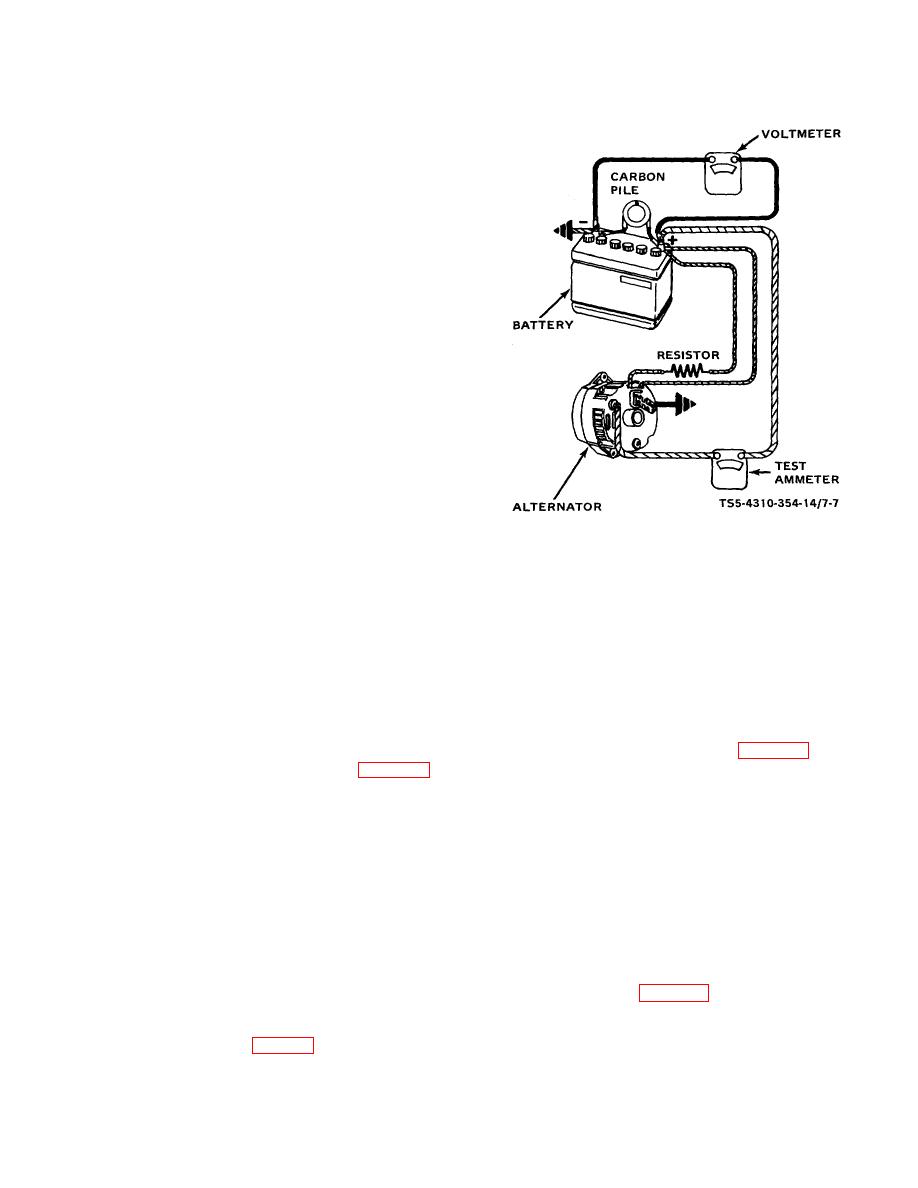
Figure 7-7. Alternator bench testing.
and bearing are clean.
Insert a pin
through hole in slip ring end frame (31) to
Overcharged Battery. If not grounded,
hold up the brushes. Carefully assemble
test regulator with an approved regulator
the end frame (31) onto rotor assembly
test or, and check field winding.
shaft aligning the scribe marks made at
disassembly. Install the through bolts (1)
NOTE
and remove the brush retaining pin to
allow brushes to drop onto slip rings.
The battery MUST be fully charged
when making this check.
assembly before installing on engine, make setup in a
(4) If voltage is below 15.5 volts, connect the
test stand and test as follows:
carbon pile as shown in figure 7-7.
(1) Make connections as shown in figure 7-7,
(5) Operate the alternator at moderate speed
except do not connect carbon pile at this
as required and adjust the carbon pile as
time. IMPORTANT: Ground polarity of
required to obtain maximum current
battery and alternator must be the same
output.
negative. Use a fully charged battery and
a 10-ohm resistor rated at six watts or
(6) If output is within 10 amperes of rated
more between alternator No. 1 terminal
output of 37 amperes (stamped on drive
and the battery.
end frame), the alternator is good.
(2) Start the test stand and slowly increase
(7) If output is not within 10 amperes of rated
the alternator speed and observe the
output, keep battery loaded with carbon
voltage.
pile and ground the alternator field as
shown in figure 7-8.
(3) If the voltage is uncontrolled with speed
and increases above 15.5 volts, check for
a grounded brush lead clip. Refer to
troubleshooting table 5-1 under heading of
7-7

