
TM 5-4310-376-14
5-11. VALVES AND SPRINGS - Continued
REMARKS
ACTION
LOCATION/lTEM
REMOVAL (Cont'd)
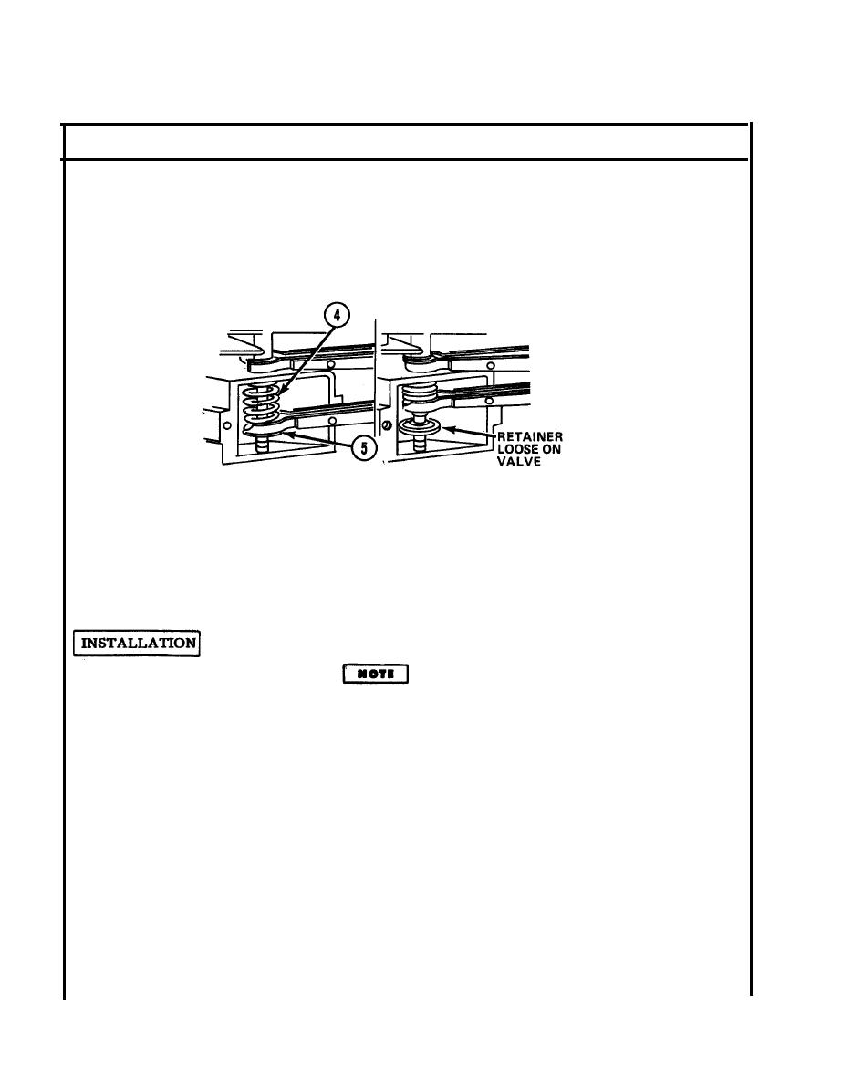
1. Exhaust valve b. Remove retainers (2) and lift out valve (3)
through top of engine.
(cont'd)
c. Pull out compressor and spring (1).
Slip upper jaw over top
2 . Intake valve a. Using a valve compressor tool, compress
of valve chamber and
spring (4).
lower jaw between
spring and retainer (5).
Tighten jaws to com-
press spring (4).
b. Remove retainer (5) and lift out valve
through top of engine.
c. Pull out compressor and spring.
Using a valve seat insert removing tool, re-
3. Valve seats
move valve seat insert.
Apply lubricant to valve stems and guides before instal-
ling. Be sure that no lubricant is on ends of valve stems
or tappets.
1. Exhaust valve a. Position spring (1) and rotator (6) in
valve chamber.
b. Install valve in its respective guide in
cylinder.
c. Using valve spring compressor tool posi-
tioned under valve rotator (6), compress
valve spring (1) until valve stem end is
through valve rotator far enough that the
retainers (2) can be installed.
d. Apply a small amount of grease to inside
of retainers (2) so that they will stick in
5-28

