
TM 5-4310-376-14
5-12. PISTON AND ROD ASSEMBLY
This task covers:
Removal, repair and installation of pistons, piston rings and connecting rods.
INITIAL SETUP
Equipment Condition
Tools
Engine removed (para 4-23) and on workbench.
Shop Set, Automotive Repair
Cylinder head removed (para 4-33).
Field Maintenance, Basic
Crankcase cover removed (para 5-15).
NSN 4910-00-754-0705
Materials and Parts
Screw lock P/N 222299
Piston (w/locks) P/N 394661
Dipper P/N 222329
Connecting rod P/N 393860
Ring set P/N 394665
Piston pin (w/lock) P/N 299691
Lubricating oil (item 4, Appendix E)
Connecting rod screw P/N 92909
REMARKS
ACTION
LOCATION/lTEM
Before removing piston and connecting rod assembly, remove
any carbon d eposits and/or wear ridge from upper end of cy-
linder bore. This will prevent breaking piston rings.
Remove any carbon or
1 . P i s t o n / C o n - a . Turn crankshaft until piston reaches low-
ridge at top of cylinder.
est position of travel in cylinder bore.
necting rod
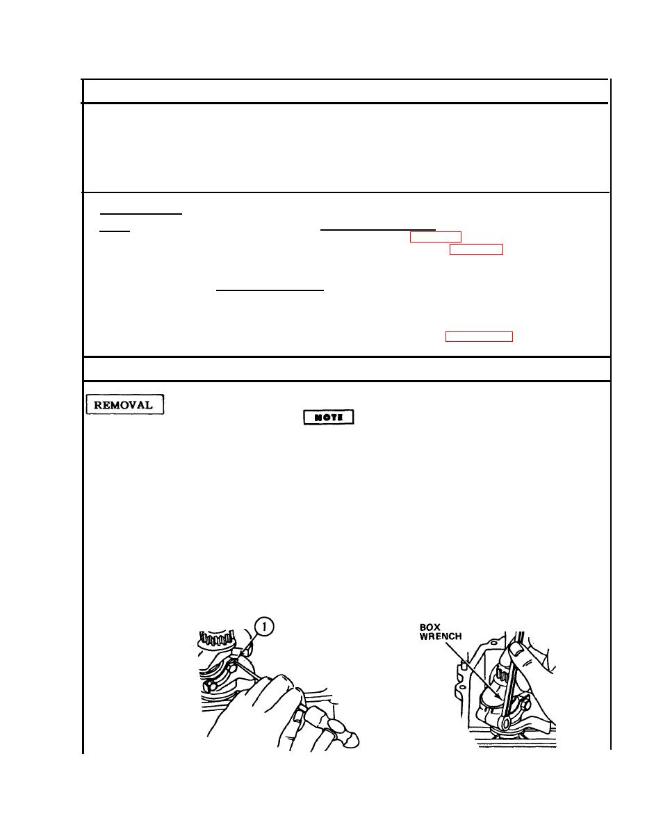
b. Using a punch and hammer, bend down
connecting rod lock tab (1).
c. Use box wrench to remove 2 screws.
d. Push piston and rod out through top
of cylinder.
5-31

