
TM 5-4310-376-14
5-12. PISTON AND ROD ASSEMBLY - Continued
REMARKS
ACTION
LOCATION/lTEM
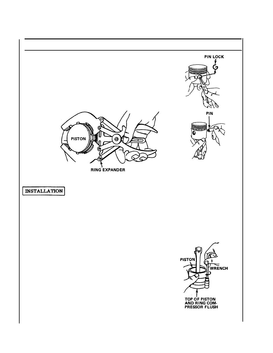
a. Use needle nose pliers and remove
2. Piston
piston pin locks.
b. Push piston pin out.
Use a piston ring expander and remove
3. Piston rings
rings one at a time, slipping them over
ring lands.
1 . P i s t o n r i n g s a . Oil rings and piston skirt.
Install oil ring first,
b. Using ring expander tool, install new
compression and scrape
piston rings in proper sequence on
ring, then the top com-
piston.
pression ring.
c . Stagger ring gaps so they are not in dir-
ect line with one another or piston pin
ends.
d. Use ring compressor, turn com-
pressor tool and piston upside
down on bench and push downward,
so piston head (top) and edge of
compressor tool band are even,
tighten compressor tool.
e. Draw compressor tool tightly to
fully compress rings, then loosen
very slightly.
5-32

