
TM 5-4310-380-13
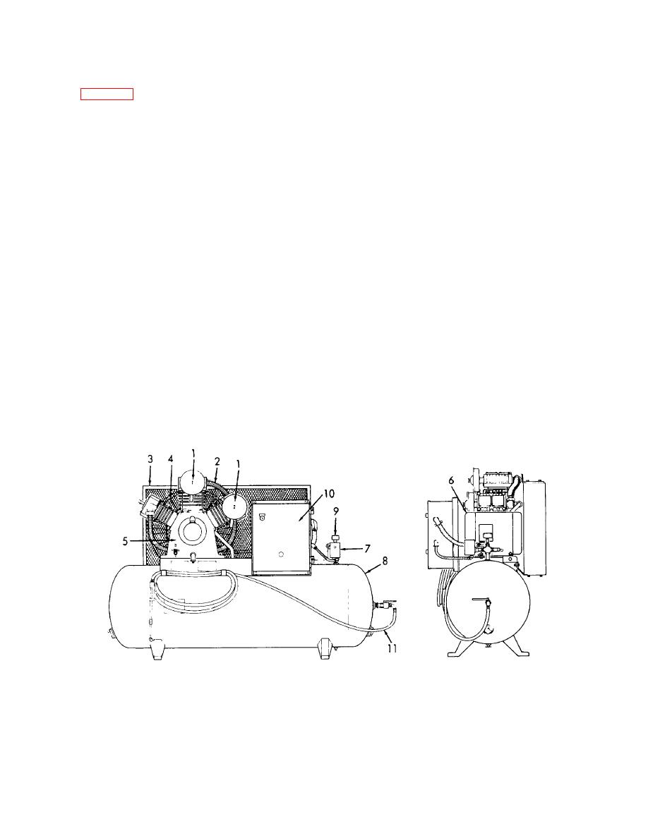
1-11. LOCATION AND DESCRIPTION OF MAJOR COMPONENTS.
(Refer to Figure 1-1)
a.
Air Intake Filters. The air intake filters (1) remove the dust and debris from the incoming air to prevent
damage to the compressor.
b.
Intercooler. The intercooler (2) cools the compressed air between the first and second stages.
c.
Belt Guard. The belt guard (3) prevents personnel and debris from getting caught in the belts.
d.
Cooling Fan. The cooling fan (4) directs cooling air to the finned intercooler and to the finned cylinders.
e.
f.
Motor. The motor (6) is a 10 hp, brushless type that provides the motive force to drive the compressor.
g.
Pressure Switch. The pressure switch (7) automatically turns on the motor at 175 psi 10 (12.3 0.70
kgs/cm ) and turns off the motor at 200 0, -10 psi (14.1 0, -0.70 kgs/cm3) to regulate the pressure in the tank.
2
h.
Air Receiver Tank. The air receiver tank (8) holds the compressed air until ready for use.
i.
Air Pressure Gage. The air pressure gage (9) reads the air pressure in the air receiver tank.
j.
Starter. The starter (10) starts and stops the motor upon command from the pressure switch.
k.
Flexible Hose.
The flexible hose (11) transfers the compressed air from the air receiver tank to where the
air will be used.
Figure 1-1. Compressor Unit, Reciprocating, 25 CFM, 175 PSI, Electric Motor Driven.
1-4

