
TM 5-4310-380-13
2-1.
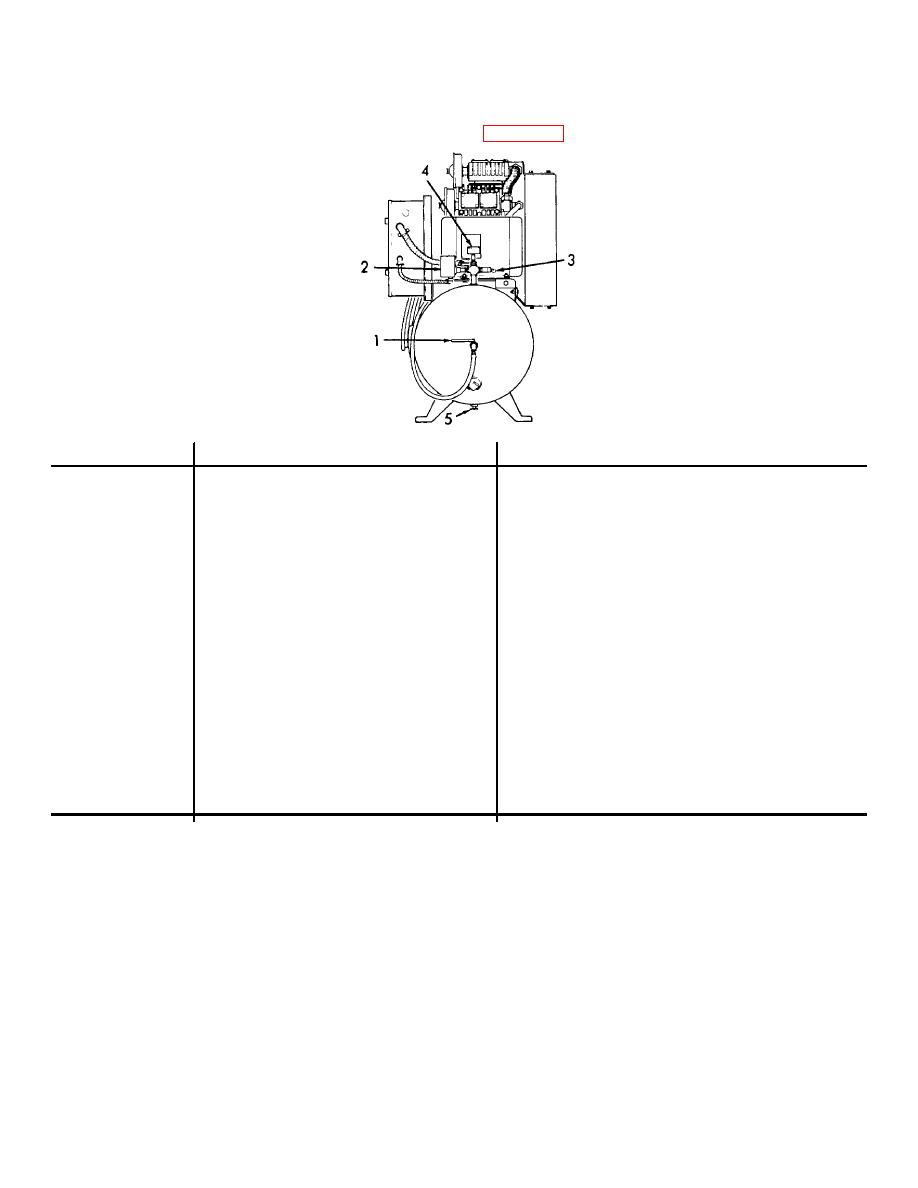
OPERATOR'S CONTROLS AND INDICATORS - Continued.
b.
KEY
CONTROL OR INDICATOR
FUNCTION
1
Air Shut-off Valve
Allows the operator to shut-off the air from the
tank to the flexible hose.
2
Pressure Switch
The pressure switch is connected directly to the
air pressure in the tank. When the air pressure
in the tank drops to 175 10 psi (12.3 0.70
kgs/cm2) the switch is actuated and causes the
motor starter to start the motor. When the air
pressure in the tank is raised to 200 0, -10 psi
(14.1 0, -0.70 kgs/cm2) the switch opens and
causes the motor starter to shut off the motor.
3
Safety Relief Valve
Allows air to escape when pressure exceeds
3
200 psi (14.1 kgs/cm ).
4
Air Pressure Gage
Provides an indication of air pressure in the
tank. The gage reads 0 to 300 psig.
5
Drain Cock
Provides a means of draining off any moisture
that may have condensed in the tank.
Figure 2-2. Air Receiver Tank, Controls and Indicators.
2-2

