
these limits, improper assembly or worn parts
and ammeter. Connect a voltmeter between the
are possible causes. Check bearing to be sure
armature and field connections.
of proper seating.
(2) Before closing battery switch, connect
ammeter to its highest range. Close battery
d. Reassembly and Installation.
switch and read ammeter. Open battery switch
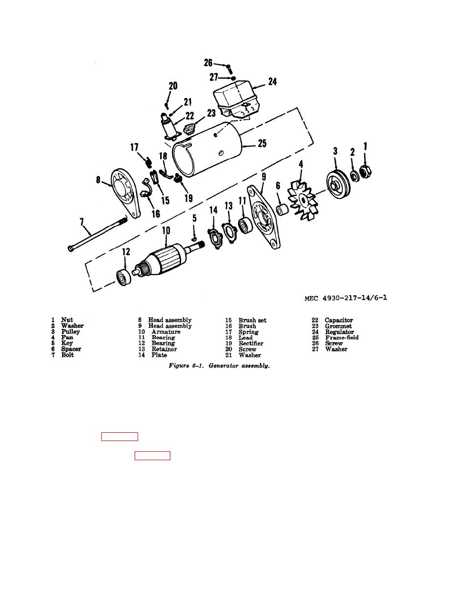
(1) Reassembly is the reverse of disas-
and connect ammeter to lowest range which
sembly, refer to figure 6-1.
will safely carry current indicated in first
(2) Installation of the generator assembly
reading.
is the reverse of removal (para 3-55).
(3) Close battery switch. Adjust variable
e. Field Current Draw Test.
resistance to produce a reading of 5 volts on
(1) Connect the generator in series with
the voltmeter. The ammeter tshould indicate
a battery, battery switch, variable resistor,
LO to 1.05 amperes.
6-2

