TM 9-4310-397-14
6-6. ROCKER ARMS, CYLINDER HEAD, AND VALVES REPLACEMENT. - Continued
CAUTION
Repositioning the cylinder head to align the head cap screws holes without the guide studs
can damage the piston o-ring seal.
(f)
Position cylinder head over guide studs and lower into place on cylinder block.
(g)
Install cylinder head cap screws in all open holes. Remove guide studs and install cap screws in their place.
(h)
Torque the 4.41 in. (112 mm) flange-head cap screws using the torque-turn method as follows:
1
Torque 63ft-lb (85 Nm) in sequence.
2
Torque 100ft-lb (135 Nm) in sequence.
3
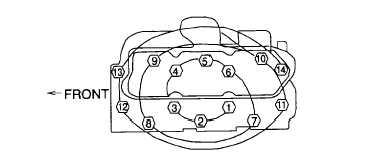
Make a mark on cylinder head next to each cap screw. Make a mark on socket and then make a second
mark 1/6 turn (60° ± 10°) counterclockwise from the first. Place socket on cap screw so that first mark on
socket aligns with mark on cylinder head. Tighten (in sequence shown on Figure 6-30) all cap screws until
second mark on socket aligns with mark on cylinder head.
Figure 6-30. Cylinder Head Torque
(3)
Assemble rocker arms on shaft.
(a)
Lubricate OD of shaft, bores of rocker arms, and rocker arm supports with clean engine oil.
(b)
Slide springs (Figure 6-23, 1) rocker arms (2), and rocker arm support (3) on shaft (4). Assemble in the
same relationship they were in before disassembly.
(c)
Install bowed washers (5) and plugs (6) on shaft (4).
(d)
Install push rods (7).
(e)
Install wear caps on valves, making certain caps rotate freely.
(f)
Position rocker arm assembly on engine. Make sure that oil supply hole of rocker arm shaft is on the
flywheel end and facing downward when rocker shaft is installed.
(g)
Lubricate all rocker arms with engine oil and make sure they move freely.
(h) Install all cap screws (8) and washers (9). Tighten attaching cap screws (8) to 35 ft-lb (47 Nm) torque.
6-30