TM 9-4310-397-14
6-8. ENGINE OIL PUMP INSPECTION, REPAIR AND REPLACEMENT.
This task covers:
a.
Removal
b.
Inspection
c.
Repair
d.
Installation
INITIAL SETUP
Tools:
Equipment Conditions:
Automotive Maintenance and Repair
Engine removed. (See para 4-72.)
Item 2, Section III, Appendix B
Oil pan removed. (See para 6-7.)
Personnel Required:
Two
a.
Removal.
(1)
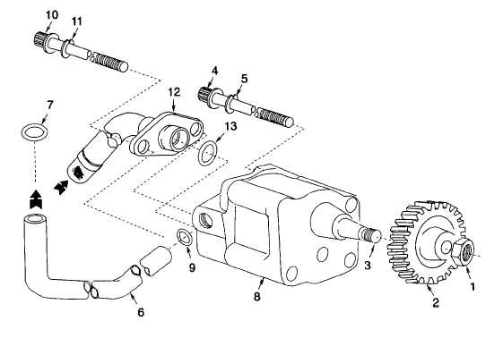
Retain gear (Figure 6-34, 2) and remove nut (1) from gear (2) and pump shaft (3).
Figure 6-34. Oil Pump
(2)
Remove three oil pump-to-front plate cap screws (4), lock washers (5) and intake tube (12). Discard lock
washers.
(3)
Remove gear (2).
6-35