SECTION II
OPERATING INSTRUCTIONS
2.1 TOWING AND POSITIONING
2.2.3
Inspect the fuel filter (see Figure 1-4); if
necessary, empty and clean the sediment bowl. Check
2.1.1 The tow bar attached to the front of the cart
the engine assembly in accordance with the instructions
enables the compressor package assembly to be
contained in Part II: of this manual.
attached to the pintle of most standard tow trucks.
Make certain the tires are uniformly inflated to a
Always make sure the foot which supports the front ends
pressure of 20 to 25 psig and that the wheel brakes are
of the cart is retracted and the wheel brakes released
set.
before attempting to tow the unit. Do not exceed a
speed of 20 miles per hour when towing on pavement;
2.3 PRE-OPERATING SERVICING
reduce speed in accordance with the condition of the
terrain. Secure the tow bar in the vertical position when
it is not being used.
2.3.1 COMPRESSOR LUBRICATION (See Figure 3-1)
2.1.1 The cart handle attached to the tow bar allows the
2.3.1.1 Make sure the compressor package assembly is
compressor package assembly to be moved manually
as level as the terrain permits, then check the level of
for short distances and for proper positioning of the
the oil in the compressor reservoir by observing the
equipment. When the unit is located in its operating or
indicator sight mounted on the side of the reservoir. If
storage location, step on the foot pedal at the front of
necessary, remove the cover and filter assembly from
the cart to drop the support foot and set the wheel
the breather assembly installed in the compressor
brakes. Secure the cart handle in the vertical position.
crankcase, and add oil to bring the level up to the FULL
mark on the indicator sight. Approximately five pints of
oil are required to fill the reservoir. Be sure to replace
2.2 PRE-OPERATING INSPECTIONS
the cover and filter assembly.
NOTE
Refer to Instruction Decal on engine
compartment access door.
2.2.1 Open all access doors and perform a thorough
general inspection of the compressor package
assembly, looking for obvious indications of damage
such as oil or air leaks, loosely mounted or missing
parts, bent or broken fins on the interstage connecting
tubes and cylinders, damaged or improperly zeroed
pressure gages, and broken safety wires. Check all
pneumatic and fuel systems connections for tightness.
Make certain all surfaces of the unit are free of
obstructions and deposits that would impair the
operation of the engine, compressor and other
components, or prevent efficient cooling of the units.
Examine the air hose, the pressure servicing valve and
the chuck for damaged fittings, swelling, rupturing, and
other indications of deterioration. Inspect the fuel tank
for dents, cracks, leaks, and other damage.
2.2.2 Remove the attaching screws and lock washers
and lift the silencer cover and intake filter from the
compressor first stage cylinder head. If necessary,
clean the filter by washing in ethyl alcohol (Federal
Specification O-A-396) and allow the element to air dry.
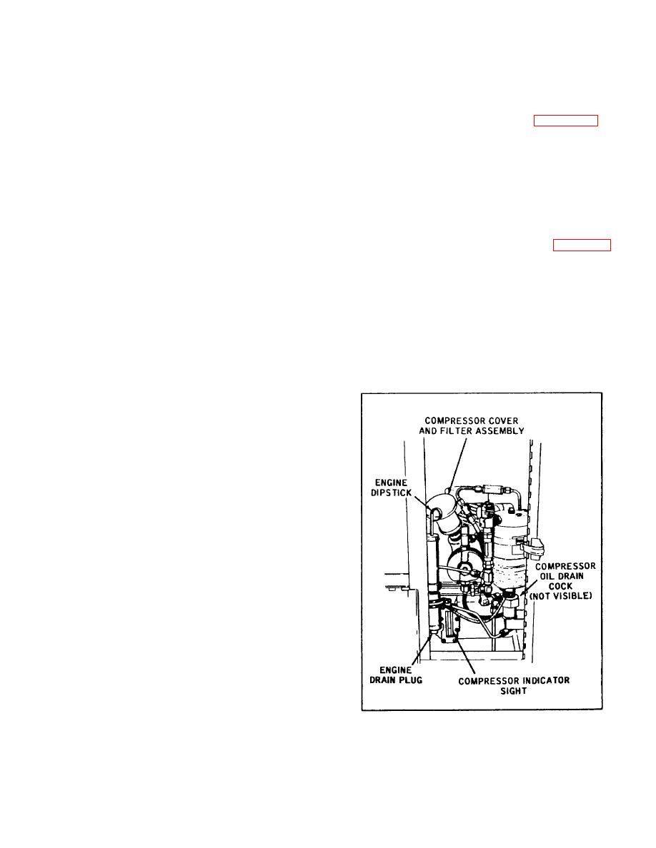
Figure 2-1. Compressor and Engine
Use a clean cloth moistened with dry-cleaning solvent
Lubrication Points
(Federal Specification P-S-661) to clean the inside of
the silencer cover, then remove all residue by wiping
with a clean, lint-free cloth. Replace the intake filter and
silencer cover on the first stage cylinder head.
15


