TM 5-4310-227-15
justing lever (15, fig. 2-8) is a manually op-
crated, tension-positioned lever used to adjust
the speed of the engine. On models BMW-
452-ENG and BMW-452-ENG-1 the gover-
nor is controlled by the knob (9, fig. 2-2). Re-
f e r to TM 5-2805-203-14 for engine data ap-
plicable to model OEG-458-ENG-3.
b. The variable speed governor is set for two
speeds. Pushed in and locked allows the en-
gine to run at idling speed. When the control
is pulled full out, the engine is set to run at
full governed speed. To set the control on
BMW-458-
m o d e l s BMW-452-ENG and
ENG-1, it is only necessary to turn the knob
to the right.
1
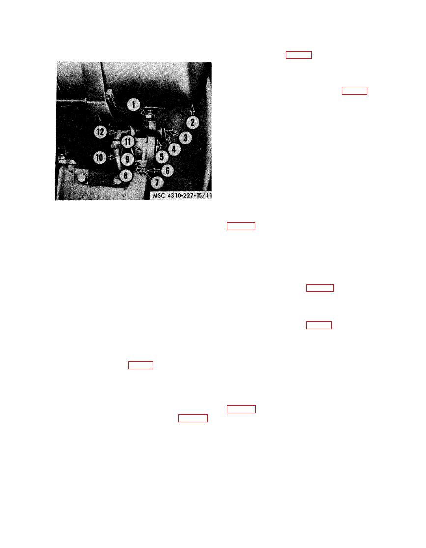
Nipple, pipe, brass 1/8-27
The engine ground switch pushbutton (17,
2
Fuel tank
Fuel shutoff valve
3
on the magneto ignition shield (13). It is a
Packing nut
4
manually operated pushbutton used to stop
Strainer cover
5
6
Bail
the engine. To stop the engine, press the push-
Bail screw nut (spec)
7
button in and hold it there until the engine
Bail screw (spec)
8
stops. The stop button for models BMW-452-
9
Knurled nut
ENG and BMW-452-ENG-1 is located on the
10
Fuel strainer-to-carburetor tube
instrument panel (2, fig. 2-2).
11
Sediment bowl
12
Elbow
OEG-458-ENG-2, and OEG-458-ENG-3,
The start button (4, fig. 2-2) models BMW-
removal points.
452-ENG and BMW-452-ENG-1, mounted on
the instrument panel, closes the starting circuit
which activates the starter to start the engine.
The choke lever (31, fig. 2-7), models OEG-
458-ENG-1 and OEG458-ENG-2, is mount-
ed on the carburetor (36). It is used to regulate
Relief Valve
the flow of air to the carburetor. It is a buter-
The air receiver tank safety relief valve (7,
fly-valve type of control. The choke for models
BMW-452-ENG and BMW-452-ENG-1 is lo-
mounted at the end of the air receiver tank on
cated on the instrument panel (3, fig. 22).
m o d e l s OEG-458-ENG-1, OEG-458-ENG-2,
Refer to TM 52805-203-14 for engine data
applicable to Model OEG-458-ENG-3.
and OEG-458-ENG-3. On models BMW-452-
ENG and BMW-452-ENG-1, it is located on
the left rear side of the air receiver tank. It is
a combination automatic and manually operat-
ed valve. It limits the amount of pressure in the
a. The governor control assembly, models
OEG-458-ENG-1 and OEG-458-ENG-2, are
tank to 185 psi. It also provides a means of re-
mounted on the drive pulley side of the cylin-
leasing tank pressure in the event of an emer-
gency or when all other outlets are in use.
der and crankcase assembly. The governor ad-


