TM 5-4310-227-15
(4) Position the gasket on the bracket
(17). Position the gasket inside the
oilcup (19).
(5) Fill the oilcup with clean oil to the
oil level mark. Do not overfill. Refer
to the current lubrication order for
the proper lubricant.
(6) Position the cap and filter assembly
(2) on the oilcup and place the air
cleaner on the bracket, Secure the
air cleaner with the wingnut (1).
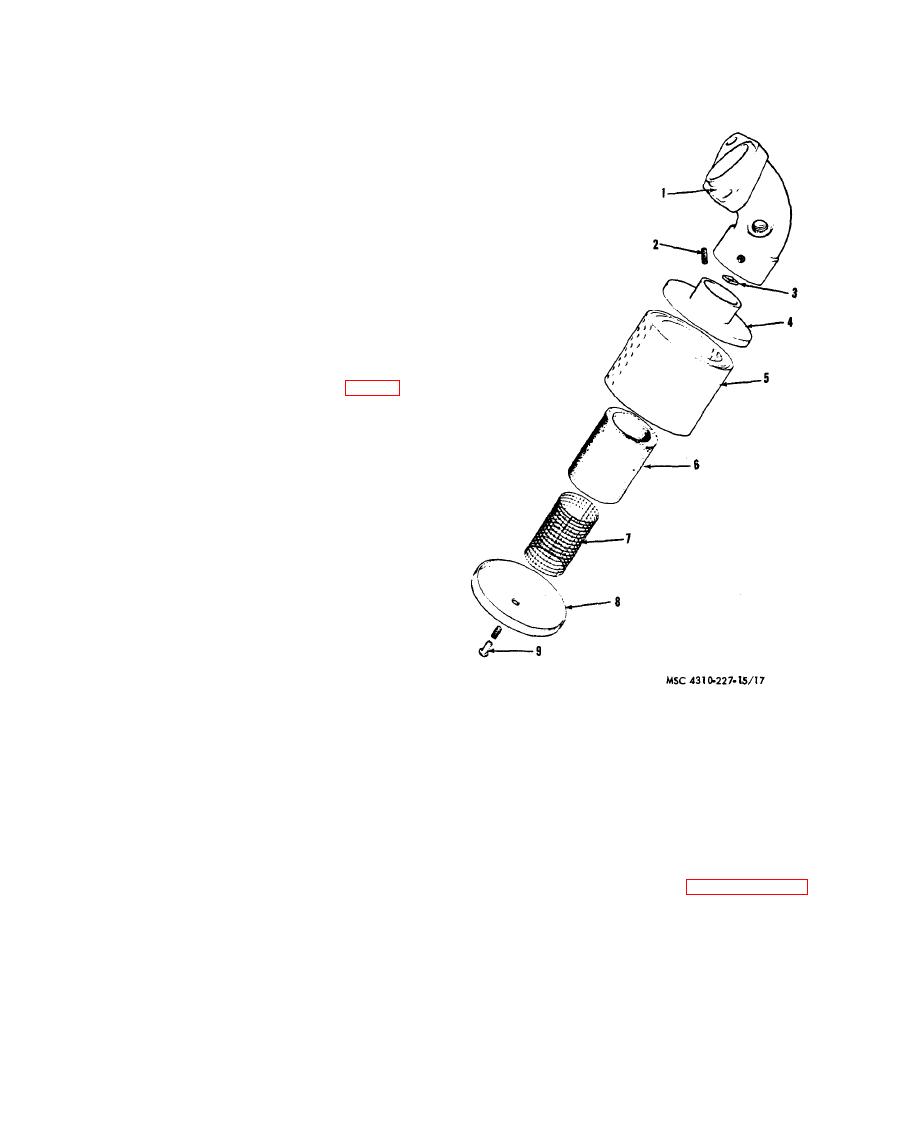
e. Compressor Air Cleaner.
(1) Loosen the setscrew (2, fig. 3-3) in
the intake manifold and remove the
intake air cleaner from the low-pres-
sure intake maifold (1).
(2) Remove the nut (3) and bolt (9).
(3) Remove the top (4) and bottom (8)
from plate (5).
(4) Remove the screen (7) and element
(6).
(5) C l e a n all parts with an approved
cleaning solvent and dry thoroughly.
(6) Install the screen (7) and element
(6) in plate (5).
(7) Install the top (4) and bottom (8).
Element, scottfoam
6
1
Manifold
7
screen
2
Setscrew
(8) Install the bolt (9) and fasten nut
8
Bottom
3
Nut
(3).
Bolt
9
4
Top
5
Plate
(9) Install the air cleaner in the manifold
(1) and tighten setscrew (2).
PREVENTIVE MAINTENANCE SERVICES
Section Ill.
are listed and described in paragraphs 3-8
3 - 7 . General
T h e item numbers indicate the
a n d 3-9.
sequence of minimum inspection requirements
To insure that the air compressor is ready
Defects discovered during operation of the unit
for operation at all times, it must be inspected
shall be noted for future correction, to be made
systematically, so that defects may be dis-
as soon as operation has ceased. Stop operation
covered and corrected before they result in
immediately if a deficiency is noted during
serious damage or failure. The necessary pre-
operation which would damage the equipment
ventive maintenance services to be performed


