TM 5-4310-227-15
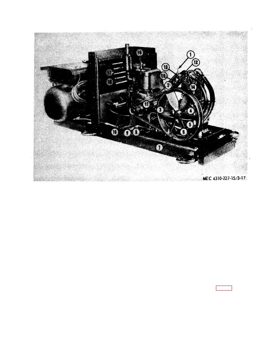
13 Stud
1
Safety valve
7 Compressor flywheel
14 Nut
2
Belt set
8 Drive pulley
15 Nut, coupling
9 Screw
9
Bolt
16 Elbow
4
Key
10 Ground cable
17 Muffler
5
Compressor crankshaft
11 Key
18 High temperature switch
6
Nut
12 High-pressure intake manifold
tilled water to a level of three-eights
of water and baking soda, if any of
inch above the plates.
the electrolyte has been spilled, or if
(4) Test the specific gravity of the elec-
the terminals are corroded, and the
battery is dirty. Rinse off with water
trolyte as prescribed in TM 9-6140-
200-15.
and dry thoroughly.
(2) Inspect the battery for cracked or
c. Installation.
broken case. Inspect the battery
(1) Install the ground cable (10) and se-
cables for worn or damaged insula-
cure with the screw (9).
tion and for loose or defective termi-
(2) Place the battery (15, fig. 3-8) in its a
nals. Replace a defective battery or
proper position and secure with the
cables.
frame (14) and nuts (13).
(3) Connect the cables (16 and 17) to the
(3) Inspect the level of the electrolyte.
battery (15).
If necessary, fill each cell with dis-
3-44


