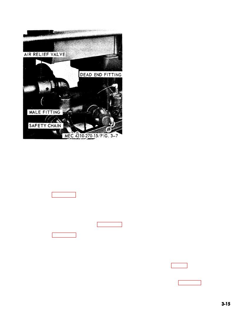
dead-end and male fittings.
b. Cleaning and Inspection.
(1) Clean both dead-end and male fittings
with an approved solvent.
(2) Clean rubber washers with an ap-
proved solvent.
(3) Inspect both dead-end and male fit-
tings for excess wear on the locking
lugs, cracks, and damaged threads.
(4) Inspect the rubber washers for cracks
and excess wear.
c. Installation.
(1) Insert the rubber washers into the
fittings.
(2) Thread the male fitting into the man-
ifold.
(3) Twist and lock dead-end fitting into
the male fitting. If the dead-end fit-
ting will not lock and is loose, replace
rubber washers.
(4) Secure safety chain to manifold.
fitting removal and installation.
a. Removal.
(1) Remove female fitting.
b. Cleaning and Inspection.
(2) Remove hose clamps.
(1) Clean air relief valve with an ap-
(3) Remove hose adapters.
proved solvent.
b. Cleaning and Inspection.
(2) Inspect for damaged threads, cracks,
(1) Clean all metal components with an
and other damage.
approved solvent.
c. Installation. Install the air relief valve as
(2) Clean the air hose with an approved
illustrated in figure 3-7.
detergent.
(3) Inspect all components for rust,
3-32. Quick Disconnect Fittings
Check
cracks, and other damage.
rubber washer for excess wear.
a. Removal.
c. Installation.
(1) Remove dead-end fitting, remove
(1) Insert adapter into ends of hose.
safety chain if required, figure 3-7.
(2) Secure adapter with hose clamps.
(2) Remove male fitting from the mani-
(3) Thread female fitting into one end
fold, figure 3-7.
of each hose.
(3) Remove rubber washer from both
Section VIII. FUEL SYSTEM
attached to the fuel tank outlet and to the
3-34. General
engine fuel filter, (fig. 3-8).
The rotary compressor is equipped with a
2 1/2 gallon fuel tank made of 18-gage terne-
3-35. Fuel line
plate. A removable wire mesh strainer is lo-
cated at the neck of the tank. The fuel tank
al of the fuel line.
cap is vented and attached to the tank with
a safety chain. A 1/4 inch nylon fuel line is


