TM 5-4310-275-14
pressure to 3300 50 psig (231.9900 3.5150 kg
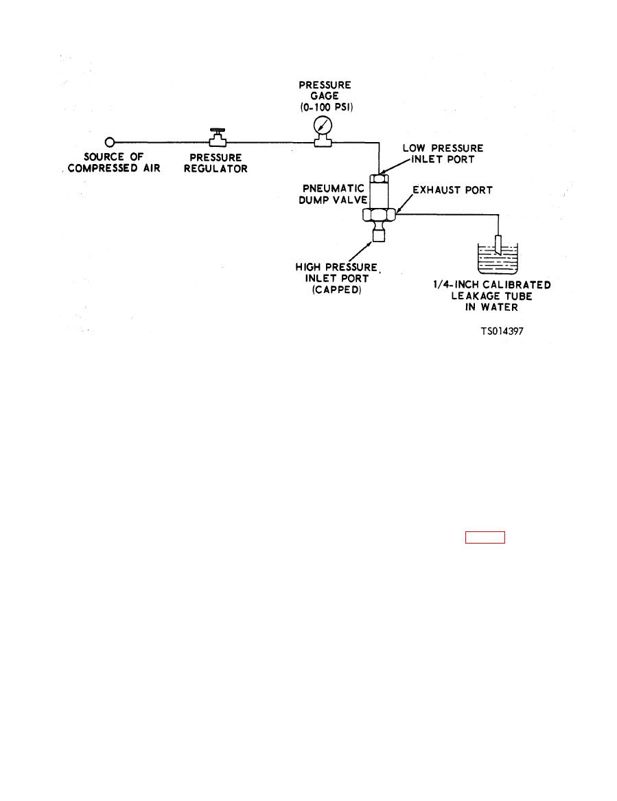
(5) Adjust pressure regulator to apply a
per sq cm), then shut off high pressure air supply.
pressure to 60 to 65 psig (4.2180 to 4.5695 kg per
sq cm) to low pressure inlet port.
(9) Piston in pneumatic dump valve should
remain closed to maintain high inlet air pressure.
(6) Leakage from exhaust port shall not
When it is evident that piston is closed, connect a
exceed three cubic centimeters per hour (one air
flowmeter to dump valve exhaust port. Measured
bubble every two minutes).
leakage shall not exceed five cubic inches per
(7) Use same test setup as illustrated in
minute.
Figure 6-9, except disconnect leakage tube from
(10) After completing tests, relieve air
exhaust port and connect an adjustable source of
pressure in test setup, disconnect pneumatic
high pressure compressed air to high pressure
dump valve and install on filter and separator
inlet port of pneumatic dump valve.
assembly.
(8) With an air pressure of 60 to 65 psig
g. Installation. Install the separator and filter
(4.2180 to 4.5695 kg per sq cm) applied to low
assembly and dump valve (fig. 4-7).
pressure inlet port, apply a gradually increasing
air pressure to high pressure inlet port. Increase


