TM 5-4310-275-14
(5) Replace all defective parts.
or excessive heat. Flash point of solvent
c. Installation.
is 100 F. (38 C.) -- 138 F. (59 C.).
(1) Refer to Figure 3-2 and install the
b. Cleaning and Inspection.
dehydrator assembly `in reverse of removal.
(1) Discard the desiccant container if the
desiccant color has faded from the characteristic
(2) Refer to Figure 3-2 and install the
blue.
desiccant container in reverse of removal.
(2) Clean all metal parts with dry cleaning
solvent, Fed. Spec. P-D-680. Dry with clean,
Back Pressure Valve Removal and In-
lint-free cloth.
stallation
(3) Clean residue from all crevices, threads,
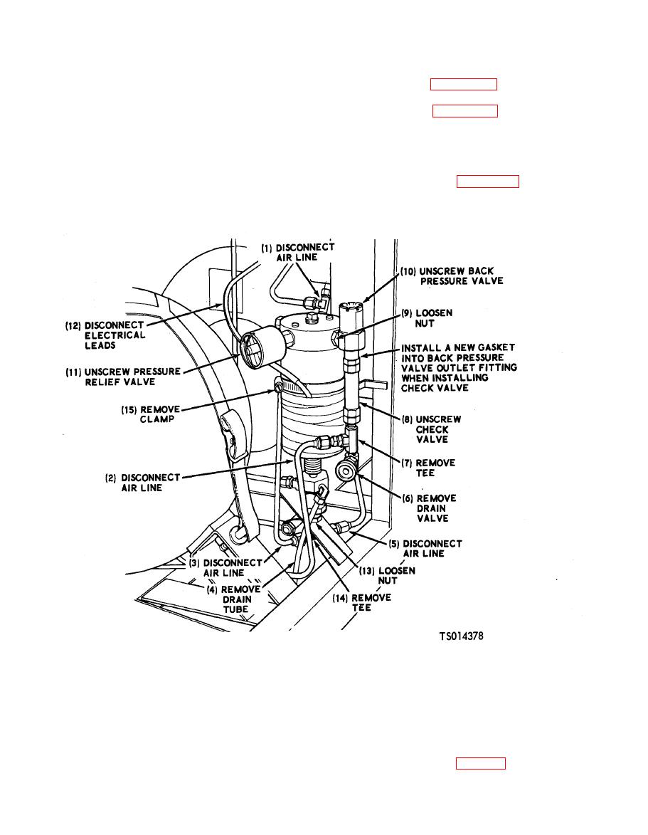
a. Removal. Refer to Figure 4-7 and remove
and air passages with compressed air.
the valve assemblies.
(4) Inspect for cracks and damaged threads.
valve, back pressure valve, removal and installation.
WARNING
b. Cleaning and Inspection.
Dry cleaning solvent, Fed. Spec. P-D-
(1) Clean exterior surfaces with a cloth
680 or P-S-661, used to clean parts is
dampened with dry cleaning solvent, Fed. Spec.
potentially dangerous to personnel and
P-D-680. Do not soak the valve assemblies.
property. Avoid repeated and prolonged
(2) Inspect for cracks and damaged threads.
skin contact. Do not use near open flame
(3) Replace a damaged valve assembly.
or exce ssiv e heat. Flash point of solvent
is 100 F. (38 C.) -- 1 3 8 F . ( 5 9 C . ) .
the valve assemblies in reverse of removal.


