TM 5-4310-335-14
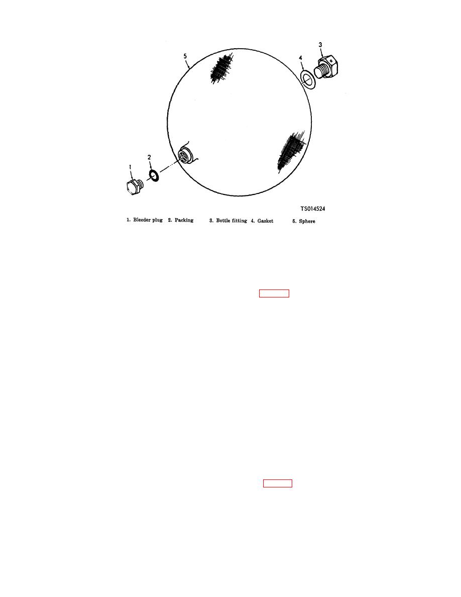
Figure 6-7. Sphere Assembly Components
2. No leakage is permissible.
(2)
Sphere Relief Valve.
(a) Assemble the valve in the reverse order of disassembly, observing the following
precautions.
threads of body (14) with grease, MIL-G- 4343B.
(c) Do not lockwire or seal the valve until testing has been completed.
(d) Test the reassembled valve as follows:
WARNING
Exercise extreme care when working with high pressure air to prevent injury to
personnel or damage to equipment. Do not attempt to tighten any fitting or perform
any work on equipment when the system is under pressure. Do not tamper with
any pressure relief valves.
1.
Assemble a plug and retainer to the outlet end of piston (6). Slowly apply a proof
pressure of 4500 psi (316.3500 kgs per sq cm) and hold for 1/2 minute. No failure or
permanent set is acceptable. Relieve the proof pressure and remove the plug.
2.
Back off relief nut (9) and adjust cap (2) until the valve passes a full flow of 18 cfm,
when a pressure of 3900 psi (274.1700 kgs per sq cm) maximum is applied. Cycle
valve 10 times from full open to zero inlet pressure. Hold cap (2) securely in place
while locking relief nut (9).
3.
Check for leakage by applying 3900 psi (274.1700 kgs per sq cm) pressure and
adjusting the inlet pressure to 3450 psi (242.5350 kgs per sq cm). Hold pressure for 1
minute to stabilize. Leakage shall not exceed 5 cc per minute.
4.
Lockwire the valve and assemble seal (1, fig. 6-8) to the lockwire.
5.
Recheck the full flow and reseat pressures after lockwiring to insure settings have not
altered.
6-5. Valve Assemblies and Timer Box Assembly
a. Disassembly.
(1) Back Pressure Valve Assembly.
6-15


