TM 5-4310-335-14
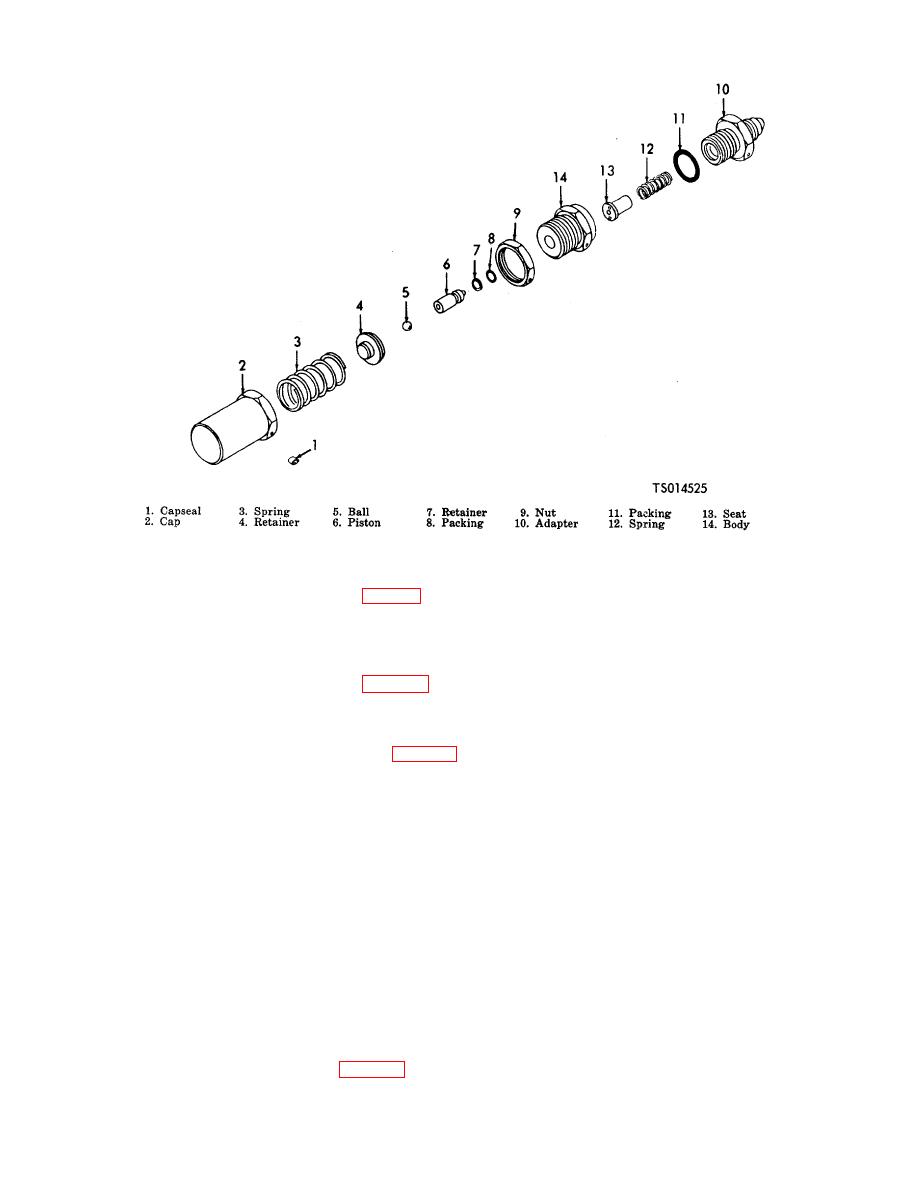
Figure 6-8. Sphere Relief Valve
(a)
Remove inlet body (2, fig. 6-9).
(b)
Remove preformed packing (3), seat (4), piston assembly (5), spring (6), shim (7), spring
seat (8), preformed packing (9), backup rings (10 and 11), preformed packing (12), backup
ring (13) and outlet body (14).
(2)
Check Valve Assembly.
(b) Remove preformed packing (3), shuttle (4), spring (5), preformed packing (6) and outlet
body (7).
(3)
Timer Box Assembly.
(b) Unscrew the large nut which holds the flexible shaft to the box (44) and remove the flexible
shaft (5). Remove the coupling (6) from the shaft.
(c) Loosen nuts (7, 15, 17 and 19) sufficiently to withdraw the nylon tubing (8, 16, 18 and 20)
from the nuts
(d) Remove grommet (9) from the box (44).
(e) Remove nuts (10), washer (11), screw (12), and washer (13) which secure the control valve
(14) to the bracket (31) and remove control valve.
(f) Remove tube nuts (7, 15, 17 and 19), elbow (21 and 22) and tee (23) from the control valve
(14).
(g) Remove nuts (24 and 25), washers (26 and 27), screws (28 and 29) and washer (30).
(h) Slide bracket (31) out of box (44).
(i) Remove nuts (32) and screws (33) which secure counter (34) to bracket (31).
(j) Loosen setscrews (35) and remove counter and spur gear (36) from the gear and cam (38).
(k) Loosen setscrew (37) and remove gear and cam (38).
(I) Remove nuts (39), washers (40), screws (41) and washers (42) which secure the gear head
reducer (43) to the bracket (31) and remove gear head reducer (43).
(4)
Unloader Valve Assembly.
6-16


