TM 5-4310-344-34
2-18.
REASSEMBLY.
regulator to Increase inlet and outlet pressure to 4800
psig. Apply a soap solution to the back pressure valve
Note
to detect external leakage allowed.
2-15. DUMP VALVE. When the dump valve is
Lubricate preformed packings with
actuated, moisture and oil vapor are purged from the air
pneumatic system grease, MIL-G-4343.
system.
a. Install preformed packing (9) into the
2-16.
groove in piston (8). Carefully slide the piston into body
(10).
a. Unscrew bulkhead union (2). Remove and
b. Install preformed packing (7) into the
discard preformed packing (3). Drop seat (4) from body
groove in end cap (5). Slide the end cap into the body
(10).
and secure with retaining ring (6).
b. Remove retaining ring (6) and pull end cap
c.
Insert seat (4) into the inlet end of the
(5) from the body.
body.
c.
Pull piston (8) from the body.
d. Install preformed packing (3) onto bulkhead
union (2). Screw the union into the body. Loosely
d.
Remove and discard preformed packings
install nut (1) onto the union.
(7 and 9).
2-19.
TESTING.
2-17.
CLEANING AND INSPECTION.
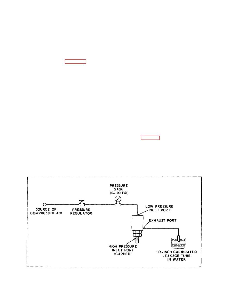
a. Install the dump valve into a test set-up as
a. Wash all parts, in dry cleaning solvent,
shown in figure 2-2.
Federal Specification P-D-680. Dry parts thoroughly
with clean, lint-free cloths and/or low-pressure
b. Adjust pressure regulator to apply a
compressed air.
pressure of 60 to 65 psig to low pressure inlet port.
b. Inspect parts for scoring, pitting, wear and
c. Leakage from exhaust port shall not
other evidence of damage.
exceed three cubic centimeters per hour (one air bubble
every two minutes).
Figure 2-2. Dump Valve Test Set-Up
2-5


