C. DRAIN COCK
G. REGULATOR AND PRESSI)RE CA('.E
The drain cock (figure 1) mounted on the underside
The regulator (figure 1) is a manually operated valve
of the air receiver tank is a manually operated valve used
controlling external air line pressure And may be
to drain compressed air and condensation from the air
adjusted within the range of 0 to 175 psi by turning the
receiver tank.
handle. A needle indicating, direct-reading, pressure
D. OIL I.EVEL GAGE
operated gage- graduated from 0 to 300 psi mounted in
The oil level gage mounted in the compressor
the regulator indicates regulator pressure setting.
crankcase ( figure 11) is a direct reading, glass covered
H. HAND-OFF-AUTOMATIC SFLECTOR SWITCH
gage used to check the level of the oil in the compressor
The hand-off-automatic: selector switch (figure 2) is
a manually actuated switch located front center of the
E. AIR RECEIVER TANK PRESSURE GAGE
magnetic switch box cover.
In OFF position the
The air receiver tank pressure gage (figure 1)
compressor motor will not operate(. When the selector
mounted on th4, side of the air receiver tank, is a needle-
is turned to AUTO position the compressor will operate
indicating, direct reading, pressure- operated gage
until pressure in air receiver tank reaches 175 psi then
graduated from 0 to 300 psi in increments of S psi. The
the pressure switch automatically shuts-off the motor.
gage indicates the air pressure in the air receiver tank.
The compressor will recycle again automatically when
Normal operating pressure is 140 to 175 psi.
pressure drops below 140 psi, and continue to cycle
F. SAFETY RELIEF VALVE
automatically in this AUTO position.
The safety relief valve (figure 1) is mounted in a tee
I. RESET BUTTON
fitting used to mount the air receiver tank pressure gage.
The reset button (figure 2) mounted on the cover of
It is a preset valve that is actuated when the air receiver
the magnetic starter, directly above the hand-off-
tank receives a pressure of 200 or more psi. This valve
automatic selector switch, is a manually operated button,
can be tripped manually by pulling up on the ring at the
which when pushed, resets the thermal relay in the
end. It is manually tripped to release pressure in the air
magnetic starter.
receiver tank and to test the valve.
SECTION IV
OPERATION UNDER USUAL CONDITIONS
2. Turn hand-off-auto selector switch (figure 2) to "off"
A. GENERAL
position.
The instructions in this section are published for the
3. Open the drain cock (figure 1) in the bottom of air
operation of the air compressor. It is essential that the
receiver tank to blow the compressed air and
operator know how to perform every operation of which
condensation from the air receiver tank.
the air compressor is capable. This section gives
4. Close drain cock.
instructions on starting and slopping, and air-pressure
adjustment.
D. AIR PRESSURE ADJUSTMENT
1. Start the air compressor (par. B above) to determine
B. STARTING
adjustment.
The pressure switch is preset by
1. Inspect the electric motor to make sure it is properly
manufacture at 140 psi CUT-IN, and 175 psi CUT-
wired from incoming power source and that power is
OUT setting. If adjustment is necessary shut off the
on.
outside power source.
2. Turn handoff-auto selector switch (figure 2) to "auto"
2. Remove cover from magnetic starter.
position.
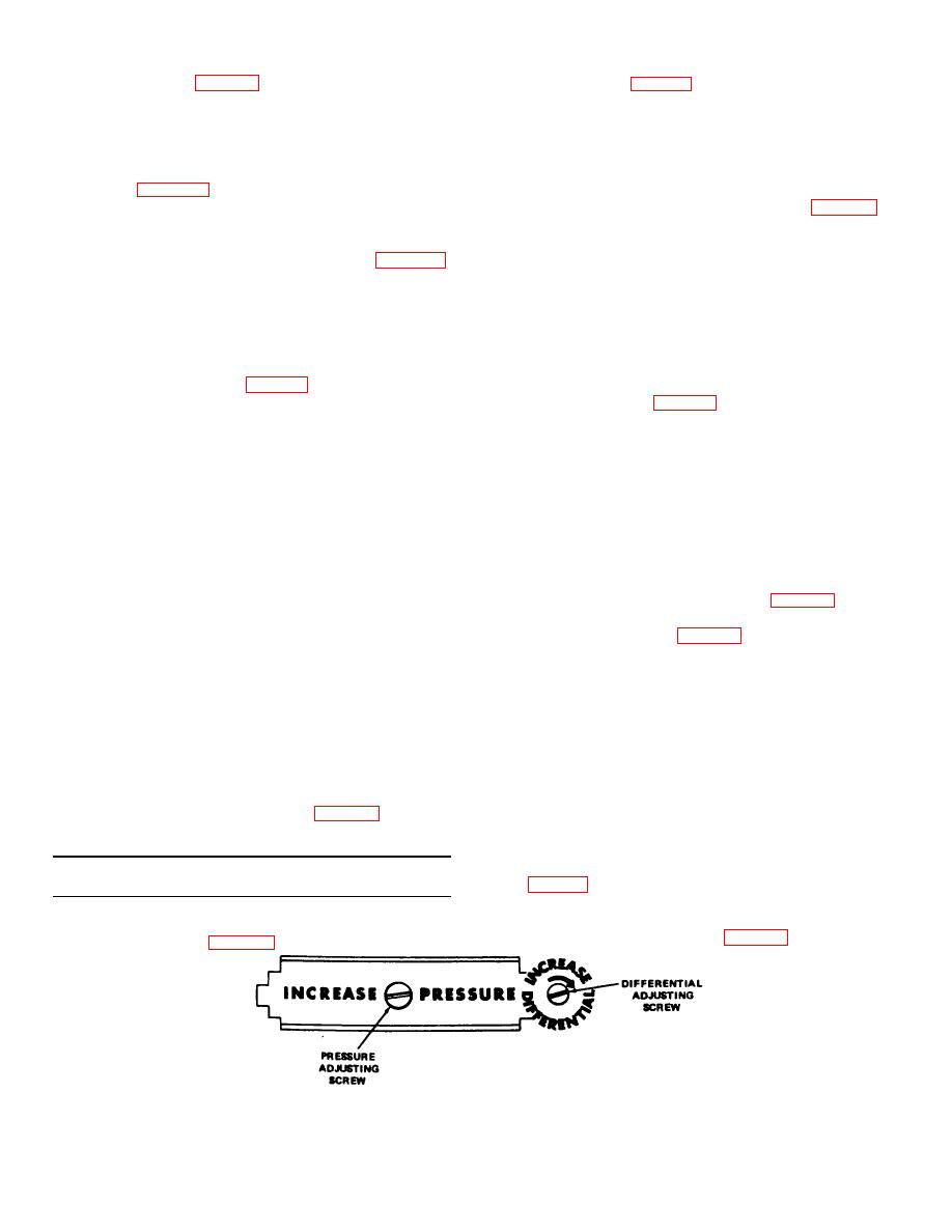
3. To raise the CUT-IN and CUT-OUT pressure turn
the pressure adjusting screw clockwise. Refer to
NOTE: Should the compressor fail to start, depress the
reset button.
4. To decrease the difference between the CUT-IN and
CUT-OUT pressure, turn the differential screw
C. STOPPING,
counter-clock-wise. Refer to figure 9.
1. Close globe valve (figure 1).
Figure 9. Pressure adjusting and differential screws.
7


