TM 5-4310-358-14
TS 4310-358-14/5-14
1.
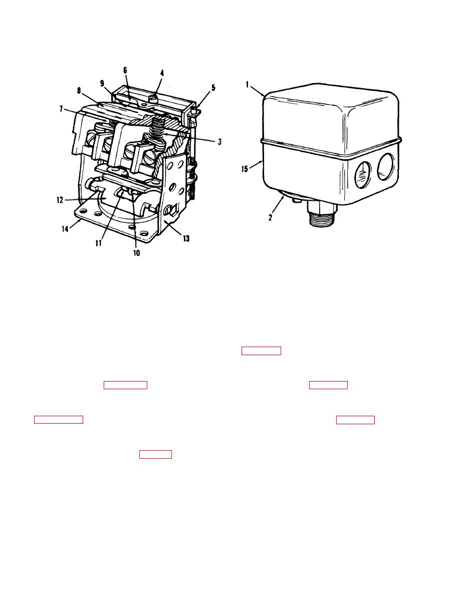
Cover
6. Bar, top
11.
Toggle
2.
Diaphragm
7. Contact board assy
12.
Lever
3.
Spring, conical
8. Spring, equalizer
13.
Plate, diaphragm
4.
Screw, pressure adjusting
9. Spring, main
14.
Frame assembly
5.
Screw and nut, differential adjusting
10. Spring, toggle
15.
Enclosure
Figure 5-14. Pressure switch assembly.
(7), conical spring (3), main spring (9), equalizer spring
turn the pressure adjusting screw clockwise.
Refer to
(8), top bar (6), in frame assembly (14), securing with
differential adjusting screw and nut (5), and pressure
adjusting screw (4). Install cover (1).
d. To increase the difference between the CUT-IN
and CUT-OUT pressure turn the differential screw
clockwise. Refer to figure 5-15.
switch reversing the removal procedure.
e. To decrease the difference between the CUT-IN
(3) Set air pressure adjustment as des cribed
and CUT-OUT pressure, turn the differential screw
counter-clockwise. Refer to figure 5-15.
5-9. Air Pressure Adjustment.
CAUTION
adjustment.
The pressure switch is preset by
When adjusting the differential
manufacturer at 165 psi CUT-IN, and 190 psi CUT-OUT
screw, do not turn it farther than it
setting. If adjustment is necessary, shut off the outside
will turn easily.
power source.
f. To increase the differential and maintain the
b. Remove cover from pressure switch.
same CUT-OUT pressure, turn the differential screw
clockwise and, at the same time, turn the pressure
c. To raise the CUT-IN and CUT-OUT pressure
adjusting screw counterclockwise.
5-27


