TM 5-4310-362-14
CYLINDER HEAD AND VALVES MODEL 20-904 (Cont)
LOCATION/ITEM
ACTION
REMARKS
4.
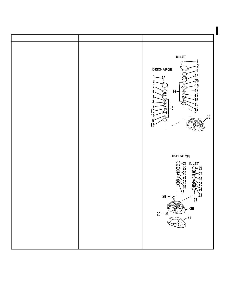
Discharge valve assembly
Install in head with valve seat
LOW PRESSURE
(5)
down.
5.
Inlet valve assembly (14)
Install with valve seat (19) up.
6.
Valve cages (4 and 13)
Install
7.
O-rings (3)
Install on valve covers (2).
CAUTION
Tighten screws evenly to
avoid breaking corners off
hold-down covers.
8.
Holddown covers (2)
a. Install with screws (1).
b. Torque screws to 10 ft-lbs.
9.
Gaskets (27)
Install in head.
10. Valve retainer (23),
a. Install in head as shown,
spring (24), valve plate
using special tools (16869)
(25) and valve seat (26)
and (16870).
b. Be careful not to catch valve
plate (25) between edges
HIGH PRESSURE
of valve retainer and seat.
11. Gaskets (22)
Install
12. Valve covers (21)
a. Install.
b. Torque to 40 ft-lbs.
13. Cylinder bores
Check to see nothing has fallen
into them before installing cylin-
der head.
14. Head (30) and gasket (31)
Install on cylinder with screws
(29 and 30).
Change 1 8-15


