TM 5-4310-370-14
TM 5-4310-370-14/5-1
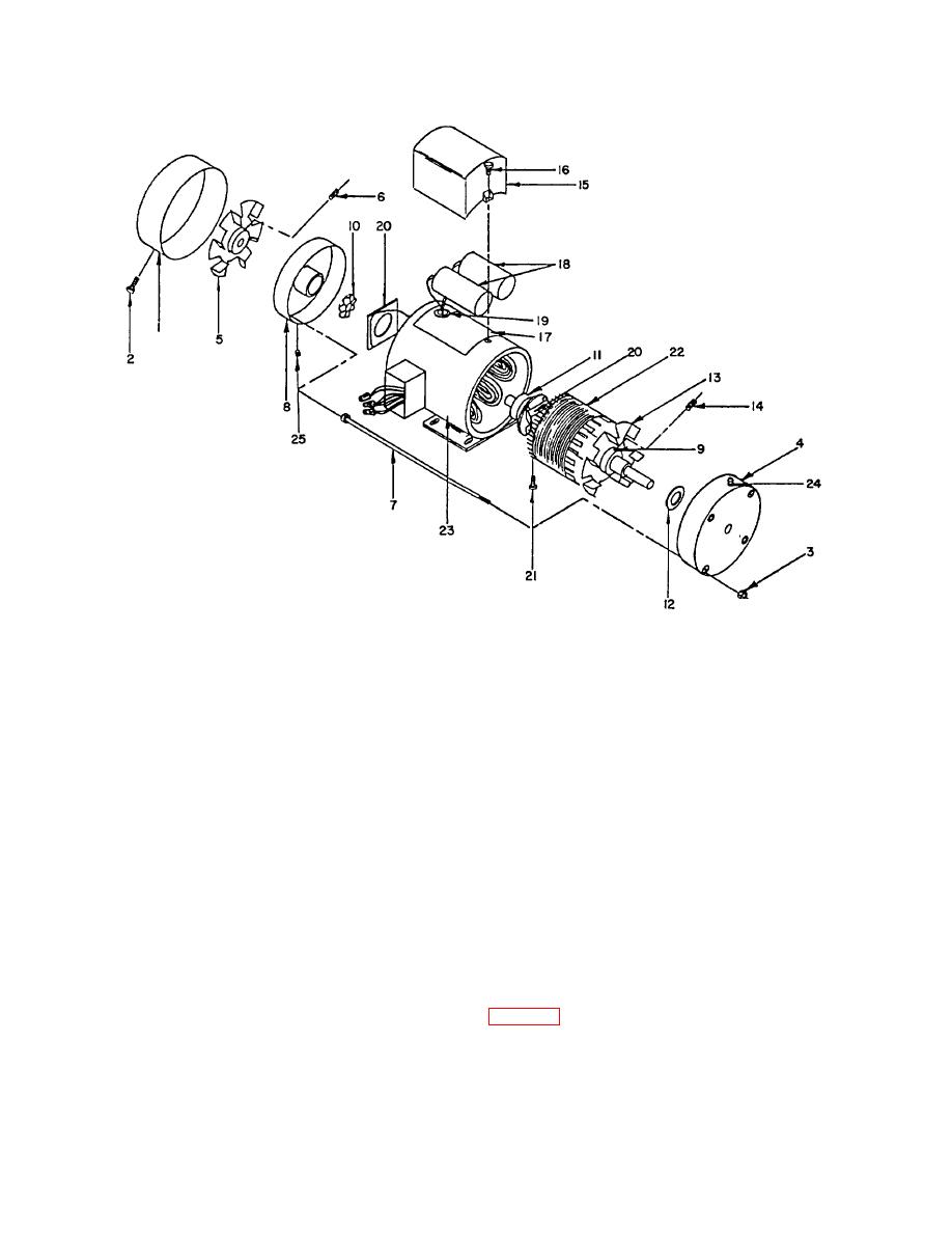
FIGURE 5-1. MOTOR ASSEMBLY
1.
Rear Housing
14.
Fan Screw
2.
Housing Screws (3)
15.
Capacitor Box
3.
Thru Bolt Nuts (4)
16.
Capacitor Box Screws (2)
4.
PU. End Plate
17.
Capacitor Box Pad
5.
Rear Fan
18.
Capacitors (2)
6.
Fan Screw
19.
Capacitor Wire Sleeve
7.
Thru Bolts (4)
20.
Switches
8.
FR. End Plate
21.
Switch Screws (4)
9.
PU. Bearing
22.
Rotor and Shaft Assembly
10.
Wavy Washer
23.
Stator
11.
FR. Bearing
24.
Front Grease Fitting
12.
Balance Washer
25.
Rear Grease Plug
13.
Front Fan
(1) All parts to be thoroughly cleaned with P-D-680 solvent, and then air dried.
(2) Inspect all parts for cracks, breaks, fissures, scores, distortions or any other applicable damage.
(3) Inspect all parts for serviceable tolerances. (See table 5-2)
5-10


