TM 5-4310-375-14
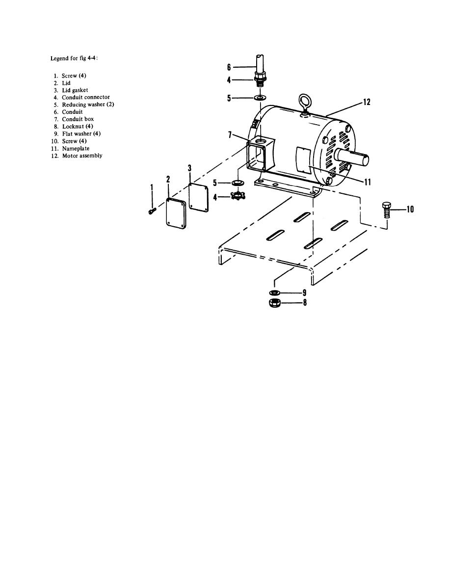
Figure 4-4. Motor assembly
Connect wire terminals T1, T2, T3 as disconnected at removal. Check all motor lead connections against
wiring instructions on nameplate (11). Reassemble lid gasket (3), lid (2) and secure with four screws (1).
(4) Turn main power source on and turn ON-OFF switch to ON position. Unit should start to run.
CAUTION
Check rotation of motor pulley. Proper rotation is clockwise when viewed
from control box side. If rotation is not correct, reverse any two power
source lead connections in control box.
4-17. Pressure switch. Maintenance of pressure switch is limited to inspection at organizational level as follows:
a . Inspection - Installed item. While unit is running, observe the air pressure gauge and note the cut-in and cut-out
pressures. Cut-in pressure should be 175 psi 10 psi (12.3 0.70 kgs/cm2) and cut-out pressure 200 psi + 0,-10 psi (14.1
+0 - 0.70 kgs/cm2). If either pressure is incorrect, notify direct support for adjustment.
4-15


