TM 5-4310-376-14
4-18. UNLOADER ASSEMBLY - Continued
LOCATION/ITEM
ACTION
REMARKS
WARNING
To avoid serious injury, use extreme
caution when working around
operating machinery. Wear eye pro-
tection and take care that loose-
fitting clothing does not become en-
tangled in the moving parts.
Start Compressor.
a.
b.
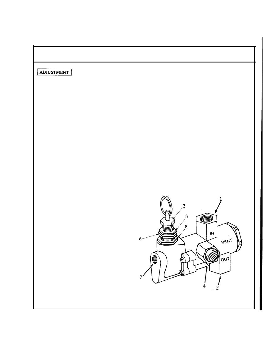
Loosen jam nuts (5) and (8).
c.
Adjust range screws (3) so that compressor goes to idle speed at
195 psi. Turn screw clockwise to increase pressure and
counterclockwise to decrease pressure.
d.
Adjust screw (6) so that compressor begins compressing air at 175
psi. Screw (6) sets the differential pressure between cut-in and cut-
out. Turning the screw clockwise will widen the differential and
turning it counterclockwise will narrow the differential.
LEGEND
1.
"IN Port-Dis-
charge from com-
pressor unloader
valve.
2.
"OUT" Port-Dis-
charge to the air
tank.
3.
Range Screw
4.
"VENT" Port-Air
vented to out-
side.
5.
Jam Nut
Differential Screw
6.
7.
Tap for engine
throttle control
8.
Jam Nut
4-36.1
Change 3


