TM 5-4310-376-14
5-11. VALVES AND SPRINGS - continued
REMARKS
ACTION
LOCATION/lTEM
INSTALLATION (Cont'd)
position on valve stem. Install retainers
1. Exhaust valve
in recess at end of valve stem.
(cont'd)
e. Slowly release valve spring compressor
Be sure retainers (2)
tool and remove it from valve chamber.
are in place.
a. Compress spring (4) and retainer (5)
2. Intake valve
Large diameter of re-
using valve spring compressor tool.
tainer (5) should face
toward front of valve
chamber.
b. Insert compressed spring and retainer into
valve chamber, drop valve stem through
large area of retainer slot.
c . Move compressor tool so as to center
small area of retainer slot onto valve
stem shoulder.
d. Release spring tension and remove com-
pressor tool from valve chamber.
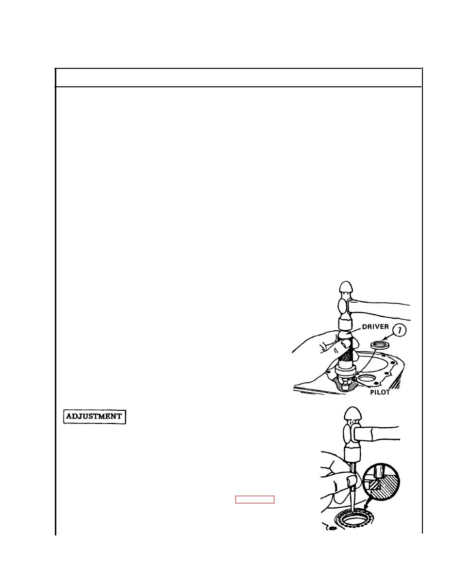
a. Position chamfered side of seat
3. Valve Seats
insert (7) down into cylinder.
b. Insert pilot into valve guide.
c . Use old insert as a spacer be-
tween driver and new insert.
d. Drive new insert until it bottoms,
top of insert will be slightly be-
low cylinder head gasket surface.
e. Peen around insert.
Check clearances cold.
a. Piston must be at top dead center
at end of compression stroke to
assure both valves being closed.
b. Insert both valves in their respec-
tive position in cylinder.
c . Check clearances (see table 5-2).
d. Grind off end of valve stem if nec-
essary, to obtain proper clearance.
5-29


