TM 5-4310-389-14
2.
Attach jumper (JU1) between terminals A and B; start engine and run at idle. If amp meter shows + and charging
voltage is present at terminal A, one or all of the diodes are defective (open).
3.
Replace or notify Direct Support for repair.
b.
Open Regulator Test.
1.
Disconnect wire from terminals extending through rear cover.
2.
Remove rear cover screws and remove rear cover.
3.
Reconnect wire removed in step 1.
4.
Turn ignition switch on but do not start engine. Ensure jumper (JU1) is not attached. Check for battery voltage
at terminals A and B. Test light will come on (figure 3-40).
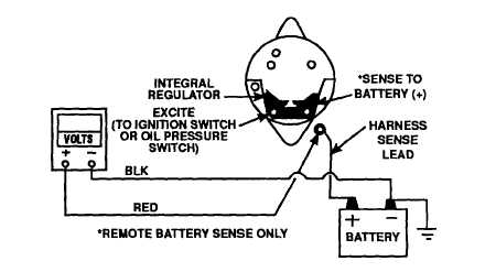
Figure 3-40. Cable Harness Voltage Test
5.
Add jumper (JU1) between field and ground. If 1.5 to 3.0 volts is present at terminal B and the amp meter shows
(-), the regulator is defective (open). If amp meter shows (+), an open field circuit is indicated.
6.
Replace or notify Direct Support for alternator repair.
c.
Harness Voltage Test.
1.
Remove ammeter (+) wire from terminal and connect multimeter as shown in figure 3-40. Meter should indicate
battery voltage (12.6 volts). If voltage is zero (0), the harness lead is open and should be repaired or replaced.
d.
Alternator Output Test.
3-71


