TM-5-4310-389-14
6.
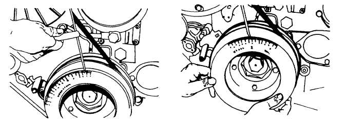
Set pointer to 0 on scale (figure 4-48).
7.
Turn crankshaft carefully in nominal direction until piston pushes up the valve. Slowly turn farther until gauge
pointer changes the direction. Set gauge at 0.
8.
Turn back crankshaft through about one revolution of gauge pointer, then again in original direction up to 0.004-
inch (0.1 mm) (10 graduations) from 0 position. Read crankshaft position from scale and record.
9.
Turn crankshaft in running direction beyond 0 through about one revolution of the gauge and turn back up to
0.004-inch (0.1 mm) (10 graduations) before 0.
10.
Read crankshaft position again from scale and record. The middle of the two crankshaft positions is the TDC
(=OT) mark.
11.
Turn crankshaft so that the mark found agrees with the pointer (003-0678). The piston is now in TDC position.
12.
Set pointer to 0 position of scale.
b.
Determining TDC without graduated scale.
NOTE
Mounted are tuning unit no. 003-0498 and dial gauge no. 003-0543. The dial gauge is pretensioned.
1.
Extend dowel sleeve by a piece of wire.
2.
Turn crankshaft carefully in normal direction until piston pushes up the valve. Slowly turn farther until gauge
pointer changes the direction. Set gauge at 0.
Figure 4-47. Securing Graduated Scale to
Figure 4-48. Zeroing Magnetic Protractor
V-Belt Pulley
4-72


